Lexus RX (RX 350L, RX450h) 2016-2026 Repair Manual: Front Fog Light Circuit
DESCRIPTION
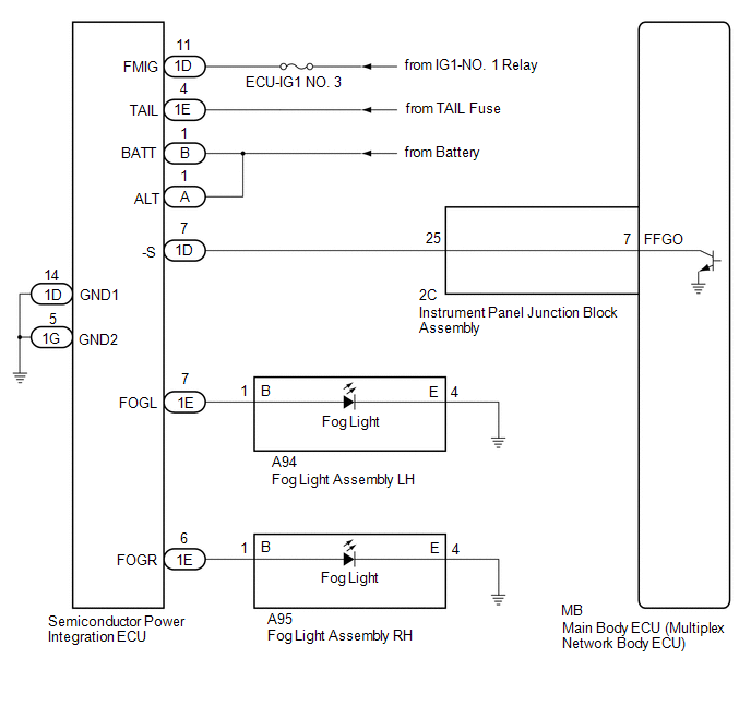
The main body ECU (multiplex network body ECU) controls the front fog lights.
WIRING DIAGRAM
CAUTION / NOTICE / HINT
NOTICE:
- Inspect the fuses for circuits related to this system before performing the following procedure.
-
Before replacing the main body ECU (multiplex network body ECU), refer to Registration.
Click here
.gif)
PROCEDURE
| 1. | CHECK OPERATION (TAILLIGHTS) |
(a) Check the operation of the taillights.
OK:
Taillights operate normally.
| NG | .gif) | GO TO PROBLEM SYMPTOMS TABLE |
|

| 2. | PERFORM ACTIVE TEST USING TECHSTREAM |
(a) Connect the Techstream to the DLC3.
(b) Turn the engine switch on (IG).
(c) Turn the Techstream on.
(d) Enter the following menus: Body Electrical / Main Body / Active Test.
(e) Perform the Active Test according to the display on the Techstream.
Body Electrical > Main Body > Active Test| Tester Display | Measurement Item | Control Range | Diagnostic Note |
|---|---|---|---|
| Front Fog Light Relay | Front fog lights | OFF/ON | Light control switch in tail position |
| Tester Display |
|---|
| Front Fog Light Relay |
OK:
Front fog light relay operates. (Front fog lights come on.)
| OK | | PROCEED TO NEXT SUSPECTED AREA SHOWN IN PROBLEM SYMPTOMS TABLE |
|
| 3. | CHECK SEMICONDUCTOR POWER INTEGRATION ECU |
(a) Using a voltmeter, check the signal reading of the semiconductor power integration ECU.
Click here
OK:
Output signal reading is normal.
| NG | | INSPECT SEMICONDUCTOR POWER INTEGRATION ECU (RESULTS OF SIGNAL READING CHECK) |
|
| 4. | CHECK HARNESS AND CONNECTOR (SEMICONDUCTOR POWER INTEGRATION ECU POWER SOURCE AND BODY GROUND) |
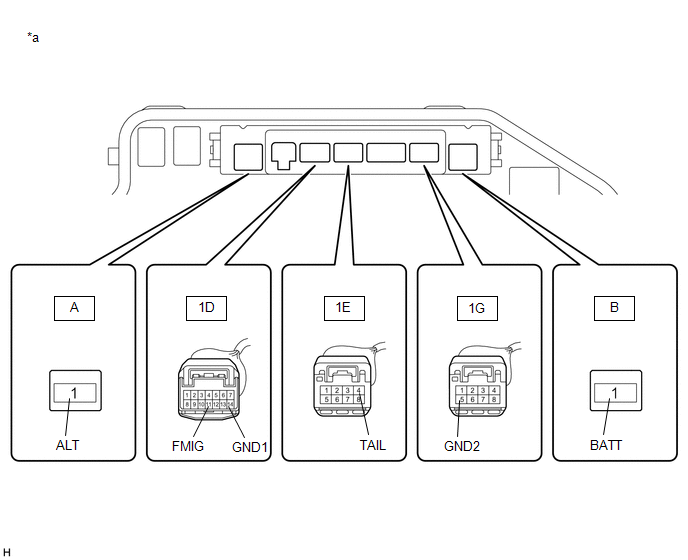
| *a | Component without semiconductor power integration ECU connected (Engine Room Relay Block and Junction Block Assembly) | - | - |
(a) Remove the semiconductor power integration ECU from the engine room relay block and junction block assembly.
Click here
(b) Measure the voltage according to the value(s) in the table below.
Standard Voltage:
| Tester Connection | Condition | Specified Condition |
|---|---|---|
| A-1 (ALT) - Body ground | Always | 11 to 14 V |
| B-1 (BATT) - Body ground | Always | 11 to 14 V |
| 1D-11 (FMIG) - Body ground | Engine switch on (IG) | 11 to 14 V |
| 1E-4 (TAIL) - Body ground | Light control switch in tail or head position | 11 to 14 V |
(c) Measure the resistance according to the value(s) in the table below.
Standard Resistance:
| Tester Connection | Condition | Specified Condition |
|---|---|---|
| 1D-14 (GND1) - Body ground | Always | Below 1 Ω |
| 1G-5 (GND2) - Body ground | Always | Below 1 Ω |
| NG | | REPAIR OR REPLACE HARNESS OR CONNECTOR |
|
| 5. | CHECK HARNESS AND CONNECTOR (SEMICONDUCTOR POWER INTEGRATION ECU - INSTRUMENT PANEL JUNCTION BLOCK ASSEMBLY) |
(a) Disconnect the 2C instrument panel junction block assembly connector.
(b) Measure the resistance according to the value(s) in the table below.
Standard Resistance:
| Tester Connection | Condition | Specified Condition |
|---|---|---|
| 1D-7 (-S) - 2C-25 | Always | Below 1 Ω |
| 1D-7 (-S) or 2C-25 - Body ground | Always | 10 kΩ or higher |
| NG | | REPAIR OR REPLACE HARNESS OR CONNECTOR |
|
| 6. | INSPECT INSTRUMENT PANEL JUNCTION BLOCK ASSEMBLY |
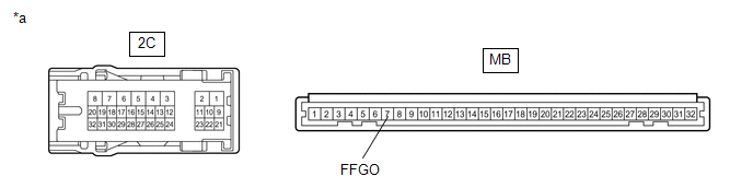
| *a | Component without harness connected (Instrument Panel Junction Block Assembly) | - | - |
(a) Remove the main body ECU (multiplex network body ECU) from the instrument panel junction block assembly.
Click here
(b) Measure the resistance according to the value(s) in the table below.
Standard Resistance:
| Tester Connection | Condition | Specified Condition |
|---|---|---|
| 2C-25 - MB-7 (FFGO) | Always | Below 1 Ω |
| NG | | REPLACE INSTRUMENT PANEL JUNCTION BLOCK ASSEMBLY |
|
| 7. | REPLACE SEMICONDUCTOR POWER INTEGRATION ECU |
(a) Replace the semiconductor power integration ECU with a new one.
Click here
|
| 8. | CHECK OPERATION (FRONT FOG LIGHTS) |
(a) Check the operation of the front fog lights.
OK:
Front fog lights operate normally.
| OK | | END (SEMICONDUCTOR POWER INTEGRATION ECU WAS DEFECTIVE) |
| NG | | REPLACE MAIN BODY ECU (MULTIPLEX NETWORK BODY ECU) |
 Parking Light/Daytime Running Light Circuit
DESCRIPTION Parking light function:
When the main body ECU (multiplex network body ECU) receives the light control switch position signal, it sends an illumination request signal to the No. 1 headl ...
 Turn Signal Light Circuit
DESCRIPTION The combination meter assembly controls the illumination and turning off of the rear turn signal lights. WIRING DIAGRAM PROCEDURE 1. CHECK OPERATION (REAR TURN SIGNAL LIGHTS) (a) ...
Other materials:
Lexus RX (RX 350L, RX450h) 2016-2026 Repair Manual > Air Conditioning System: Ambient Temperature Sensor Circuit (B1412/12)
DESCRIPTION The cooler (ambient temp. sensor) thermistor is installed in front of the cooler condenser assembly to detect the ambient temperature, which is used to control the air conditioning system. This sensor is connected to the air conditioning amplifier assembly and detects fluctuations in the ...
Lexus RX (RX 350L, RX450h) 2016-2026 Repair Manual > Rear No. 1 Seat Inner Belt Assembly(for 60/40 Split Seat Type Lh Side): Installation
INSTALLATION PROCEDURE 1. INSTALL REAR SEAT INNER BELT ASSEMBLY LH (a) Install the rear seat inner belt assembly LH with the bolt. Torque: 42 N·m {428 kgf·cm, 31 ft·lbf} NOTICE: Do not allow the anchor part of the rear seat inner belt assembly LH to overlap the protruding parts of the rear seat ...
Lexus RX (RX 350L, RX450h) 2016-{YEAR} Owners Manual
- For your information
- Pictorial index
- For safety and security
- Instrument cluster
- Operation of each component
- Driving
- Lexus Display Audio system
- Interior features
- Maintenance and care
- When trouble arises
- Vehicle specifications
- For owners
Lexus RX (RX 350L, RX450h) 2016-{YEAR} Repair Manual

0.0124