Lexus RX (RX 350L, RX450h) 2016-2026 Repair Manual: Ambient Temperature Sensor Circuit (B1412/12)
DESCRIPTION
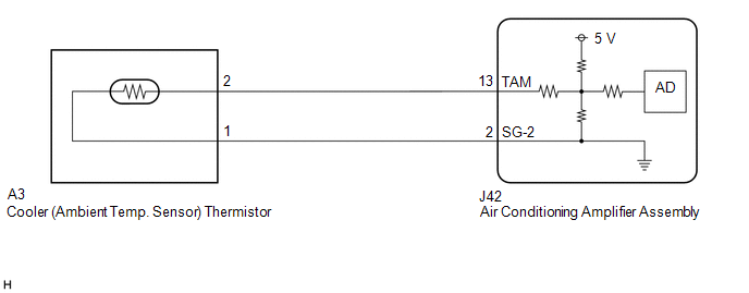
The cooler (ambient temp. sensor) thermistor is installed in front of the cooler condenser assembly to detect the ambient temperature, which is used to control the air conditioning system. This sensor is connected to the air conditioning amplifier assembly and detects fluctuations in the ambient temperature. This data is used for controlling the cabin temperature. The sensor sends a signal to the air conditioning amplifier assembly. The resistance of the cooler (ambient temp. sensor) thermistor changes in accordance with the ambient temperature. As the temperature decreases, the resistance increases. As the temperature increases, the resistance decreases.
The air conditioning amplifier assembly applies voltage (3.3 V) to the cooler (ambient temp. sensor) thermistor and reads voltage changes due to changes in the resistance of the cooler (ambient temp. sensor) thermistor.
| DTC No. | Detection Item | DTC Detection Condition | Trouble Area | Memory |
|---|---|---|---|---|
| B1412/12 | Ambient Temperature Sensor Circuit | Open or short in ambient temperature sensor circuit |
| Memorized (4 sec. or more)* |
- *: The air conditioning amplifier assembly stores this DTC if the malfunction has occurred for the period of time indicated in the brackets.
HINT:
If the ambient temperature is approximately -52.9°C (-63.22°F) or lower, DTC B1412/12 may be output even though the system is normal.
WIRING DIAGRAM
PROCEDURE
| 1. | READ VALUE USING TECHSTREAM |
(a) Connect the Techstream to the DLC3.
(b) Turn the engine switch on (IG).
(c) Turn the Techstream on.
(d) Enter the following menus: Body Electrical / Air Conditioner / Data List.
(e) Read the Data List according to the display on the Techstream.
Body Electrical > Air Conditioner > Data List| Tester Display | Measurement Item | Range | Normal Condition | Diagnostic Note |
|---|---|---|---|---|
| Ambient Temp Sensor | Cooler (ambient temp. sensor) thermistor | Min.: -23.30°C (-9.94°F) Max.: 65.95°C (150.71°F) | Actual ambient temperature displayed | - |
| Tester Display |
|---|
| Ambient Temp Sensor |
OK:
The display is as specified in the normal condition column.
| OK | .gif) | REPLACE AIR CONDITIONING AMPLIFIER ASSEMBLY |
.gif)
|
.gif)
| 2. | INSPECT COOLER (AMBIENT TEMP. SENSOR) THERMISTOR |
| (a) Remove the cooler (ambient temp. sensor) thermistor. Click here |
|
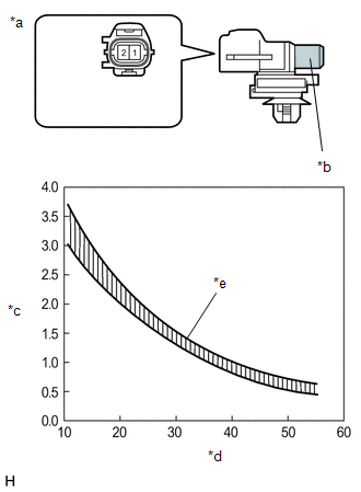
(b) Measure the resistance according to the value(s) in the table below.
Standard Resistance:
| Tester Connection | Condition | Specified Condition |
|---|---|---|
| 1 - 2 | 10°C (50°F) | 3.00 to 3.73 kΩ |
| 15°C (59°F) | 2.45 to 2.88 kΩ | |
| 20°C (68°F) | 1.95 to 2.30 kΩ | |
| 25°C (77°F) | 1.60 to 1.80 kΩ | |
| 30°C (86°F) | 1.28 to 1.47 kΩ | |
| 35°C (95°F) | 1.00 to 1.22 kΩ | |
| 40°C (104°F) | 0.80 to 1.00 kΩ | |
| 45°C (113°F) | 0.65 to 0.85 kΩ | |
| 50°C (122°F) | 0.50 to 0.70 kΩ | |
| 55°C (131°F) | 0.44 to 0.60 kΩ | |
| 60°C (140°F) | 0.36 to 0.50 kΩ |
NOTICE:
- Hold the sensor only by its connector. Touching the sensing portion may change the resistance value.
- When measuring, the sensor temperature must be the same as the ambient temperature.
HINT:
As the temperature increases, the resistance decreases (see the graph).
| NG | | REPLACE COOLER (AMBIENT TEMP. SENSOR) THERMISTOR |
|
| 3. | CHECK HARNESS AND CONNECTOR (COOLER (AMBIENT TEMP. SENSOR) THERMISTOR - AIR CONDITIONING AMPLIFIER ASSEMBLY) |
(a) Disconnect the J42 air conditioning amplifier assembly connector.
(b) Measure the resistance according to the value(s) in the table below.
Standard Resistance:
| Tester Connection | Condition | Specified Condition |
|---|---|---|
| J42-13 (TAM) - A3-2 | Always | Below 1 Ω |
| J42-2 (SG-2) - A3-1 | Always | Below 1 Ω |
| J42-13 (TAM) or A3-2 - Body ground | Always | 10 kΩ or higher |
| J42-2 (SG-2) or A3-1 - Body ground | Always | 10 kΩ or higher |
| OK | | REPLACE AIR CONDITIONING AMPLIFIER ASSEMBLY |
| NG | | REPAIR OR REPLACE HARNESS OR CONNECTOR |
 Diagnostic Trouble Code Chart
DIAGNOSTIC TROUBLE CODE CHART Air Conditioning System DTC No. Detection Item DTC Detection Condition Link B1411/11 Room Temperature Sensor Circuit Open or short in room temperature se ...
 Evaporator Temperature Sensor Circuit (B1413/13)
DESCRIPTION The No. 1 cooler thermistor is installed to the evaporator in the air conditioner unit to detect the temperature of the cooled air that has passed through the evaporator, which is used to ...
Other materials:
Lexus RX (RX 350L, RX450h) 2016-2026 Repair Manual > Emission Control System: On-vehicle Inspection
ON-VEHICLE INSPECTION CAUTION / NOTICE / HINT CAUTION: To prevent injury due to contact with an operating V-ribbed belt or cooling fan, keep your hands and clothing away from the V-ribbed belt and cooling fans when working in the engine compartment with the engine running or the engine switch on (IG ...
Lexus RX (RX 350L, RX450h) 2016-2026 Repair Manual > Front Power Seat Control System (w/ Memory): Customize Parameters
CUSTOMIZE PARAMETERS CUSTOMIZE FRONT POWER SEAT CONTROL SYSTEM (w/ Memory) HINT: The following items can be customized. NOTICE:
When the customer requests a change in a function, first make sure that the function can be customized.
Record the current settings before customizing.
(a) Customiz ...
Lexus RX (RX 350L, RX450h) 2016-{YEAR} Owners Manual
- For your information
- Pictorial index
- For safety and security
- Instrument cluster
- Operation of each component
- Driving
- Lexus Display Audio system
- Interior features
- Maintenance and care
- When trouble arises
- Vehicle specifications
- For owners
Lexus RX (RX 350L, RX450h) 2016-{YEAR} Repair Manual

0.0106