Lexus RX (RX 350L, RX450h) 2016-2026 Repair Manual: Evaporator Temperature Sensor Circuit (B1413/13)
DESCRIPTION
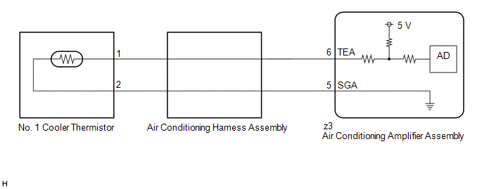
The No. 1 cooler thermistor is installed to the evaporator in the air conditioner unit to detect the temperature of the cooled air that has passed through the evaporator, which is used to control the air conditioning system. It sends signals to the air conditioning amplifier assembly. The resistance of the No. 1 cooler thermistor changes in accordance with the temperature of the cooled air that has passed through the evaporator. As the temperature decreases, the resistance increases. As the temperature increases, the resistance decreases.
The air conditioning amplifier assembly applies voltage (5 V) to the No. 1 cooler thermistor and reads voltage changes as the resistance of the No. 1 cooler thermistor changes. This sensor is used for frost prevention.
| DTC No. | Detection Item | DTC Detection Condition | Trouble Area | Memory |
|---|---|---|---|---|
| B1413/13 | Evaporator Temperature Sensor Circuit | Open or short in evaporator temperature sensor circuit |
| Memorized (4 sec. or more)* |
- *: The air conditioning amplifier assembly stores this DTC if the malfunction has occurred for the period of time indicated in the brackets.
WIRING DIAGRAM
PROCEDURE
| 1. | READ VALUE USING TECHSTREAM |
(a) Connect the Techstream to the DLC3.
(b) Turn the engine switch on (IG).
(c) Turn the Techstream on.
(d) Enter the following menus: Body Electrical / Air Conditioner / Data List.
(e) Read the Data List according to the display on the Techstream.
Body Electrical > Air Conditioner > Data List| Tester Display | Measurement Item | Range | Normal Condition | Diagnostic Note |
|---|---|---|---|---|
| Evaporator Fin Thermistor | No. 1 cooler thermistor | Min.: -29.70°C (-21.46°F) Max.: 59.55°C (139.19°F) | Actual evaporator temperature displayed | - |
| Tester Display |
|---|
| Evaporator Fin Thermistor |
OK:
The display is as specified in the normal condition column.
| Result | Proceed to |
|---|---|
| NG | A |
| OK (When troubleshooting according to Problem Symptoms Table) | B |
| OK (When troubleshooting according to the DTC) | C |
| B | .gif) | PROCEED TO NEXT SUSPECTED AREA SHOWN IN PROBLEM SYMPTOMS TABLE |
| C | | REPLACE AIR CONDITIONING AMPLIFIER ASSEMBLY |
|
.gif)
| 2. | INSPECT NO. 1 COOLER THERMISTOR |
(a) Remove the No. 1 cooler thermistor.
Click here .gif)
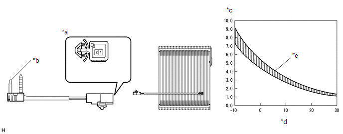
| *a | Component without harness connected (No. 1 Cooler Thermistor) | *b | Sensing Portion |
| *c | Resistance (kΩ) | *d | Temperature (°C (°F)) |
| *e | Allowable Range | - | - |
(b) Measure the resistance according to the value(s) in the table below.
Standard Resistance:
| Tester Connection | Condition | Specified Condition |
|---|---|---|
| 1 - 2 | -10°C (14°F) | 7.30 to 9.10 kΩ |
| -5°C (23°F) | 5.65 to 6.95 kΩ | |
| 0°C (32°F) | 4.40 to 5.35 kΩ | |
| 5°C (41°F) | 3.40 to 4.15 kΩ | |
| 10°C (50°F) | 2.70 to 3.25 kΩ | |
| 15°C (59°F) | 2.14 to 2.58 kΩ | |
| 20°C (68°F) | 1.71 to 2.05 kΩ | |
| 25°C (77°F) | 1.38 to 1.64 kΩ | |
| 30°C (86°F) | 1.11 to 1.32 kΩ |
NOTICE:
- Hold the sensor only by its connector. Touching the sensing portion may change the resistance value.
- When measuring, the sensor temperature must be the same as the ambient temperature.
HINT:
As the temperature increases, the resistance decreases (see the graph).
| NG | | REPLACE NO. 1 COOLER THERMISTOR |
|
| 3. | INSPECT AIR CONDITIONING HARNESS ASSEMBLY |
(a) Remove the air conditioning harness assembly.
Click here
(b) Measure the resistance according to the value(s) in the table below.
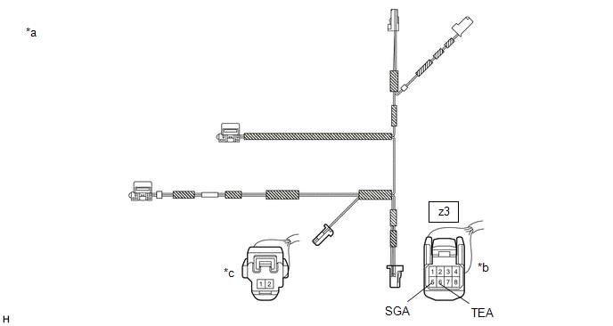
| *a | Air Conditioning Harness Assembly | *b | Front view of wire harness connector (to Air Conditioning Amplifier Assembly) |
| *c | Front view of wire harness connector (to No. 1 Cooler Thermistor) | - | - |
Standard Resistance:
| Tester Connection | Condition | Specified Condition |
|---|---|---|
| z3-5 (SGA) - 2 | Always | Below 1 Ω |
| z3-6 (TEA) - 1 | Always | Below 1 Ω |
| OK | | REPLACE AIR CONDITIONING AMPLIFIER ASSEMBLY |
| NG | | REPLACE AIR CONDITIONING HARNESS ASSEMBLY |
 Ambient Temperature Sensor Circuit (B1412/12)
DESCRIPTION The cooler (ambient temp. sensor) thermistor is installed in front of the cooler condenser assembly to detect the ambient temperature, which is used to control the air conditioning system. ...
 Evaporator Temperature Circuit (B1417/17)
DESCRIPTION The No. 2 air conditioning harness assembly is installed on the evaporator in the rear air conditioner unit to detect the temperature of the cooled air that has passed through the evaporat ...
Other materials:
Lexus RX (RX 350L, RX450h) 2016-2026 Repair Manual > Rear No. 2 Seat Assembly: Components
COMPONENTS ILLUSTRATION *1 DECK BOARD ASSEMBLY *2 NO. 1 DECK BOARD *3 REAR NO. 4 FLOOR BOARD *4 TONNEAU COVER ASSEMBLY ILLUSTRATION *A w/o Woofer *B w/ Woofer *1 DECK SIDE TRIM BOX LH *2 FRONT DECK FLOOR BOX *3 REAR DECK FLOOR BOX *4 REAR FLOOR FI ...
Lexus RX (RX 350L, RX450h) 2016-2026 Repair Manual > Side Turn Signal Light Assembly: Components
COMPONENTS ILLUSTRATION *1 NO. 1 OUTER MIRROR COVER *2 NO. 2 OUTER MIRROR COVER *3 OUTER MIRROR *4 OUTER MIRROR HOLE COVER *5 SIDE TURN SIGNAL LIGHT ASSEMBLY - - ...
Lexus RX (RX 350L, RX450h) 2016-{YEAR} Owners Manual
- For your information
- Pictorial index
- For safety and security
- Instrument cluster
- Operation of each component
- Driving
- Lexus Display Audio system
- Interior features
- Maintenance and care
- When trouble arises
- Vehicle specifications
- For owners
Lexus RX (RX 350L, RX450h) 2016-{YEAR} Repair Manual

0.0117