Lexus RX (RX 350L, RX450h) 2016-2026 Repair Manual: Terminals Of Ecu
TERMINALS OF ECU
CHECK 4WD ECU ASSEMBLY
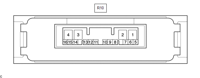
(a) Measure the voltage and resistance of the connector.
| Terminal No. (Symbol) | Wiring Color | Terminal Description | Condition | Specified Condition |
|---|---|---|---|---|
| R10-10 (4WDS) - R10-4 (GND) | P - W-B | AWD lock mode switch signal | Engine switch on (IG) AWD lock mode switch released → pressed and held | 11 to 14 V → Below 1 V |
| R10-6 (CANH) - R10-5 (CANL) | B - W | HIGH-level CAN bus wire - LOW-level CAN bus wire | Cable disconnected from negative (-) battery terminal | 54 to 69 Ω |
| R10-4 (GND) - Body ground | W-B - Body ground | Ground | Always | Below 1 Ω |
| R10-3 (IG1) - R10-4 (GND) | B - W-B | Power source voltage | Engine switch on (IG) | 11 to 14 V |
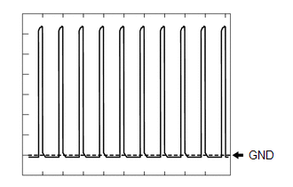
| R10-2 (SLC+) - R10-1 (SLC-) | L - B | 4WD linear solenoid signal | Shift lever in D, engine idling | Pulse generation (See waveform 1) |
If the result is not as specified, the 4WD ECU assembly may have a malfunction.
(b) Using an oscilloscope, check the waveform 1.
Waveform 1 (Reference)| Item | Content |
|---|---|
| Terminal No. (Symbol) | R10-2 (SLC+) - R10-1 (SLC-) |
| Tester Range | 2 V/DIV., 1 msec./DIV. |
| Condition | Shift lever in D, engine idling |
 Diagnosis System
DIAGNOSIS SYSTEM DESCRIPTION Dynamic torque control AWD system data and Diagnostic Trouble Codes (DTCs) can be read through the Data Link Connector 3 (DLC3) of the vehicle. When the system seems to be ...
 Dtc Check / Clear
DTC CHECK / CLEAR CHECK DTC (a) Check for DTCs. (1) Connect the Techstream to the DLC3. (2) Turn the engine switch on (IG). (3) Turn the Techstream on. (4) Read the DTCs following the prompts on the T ...
Other materials:
Lexus RX (RX 350L, RX450h) 2016-2026 Repair Manual > Rear Seat Inner Belt Assembly(for Lh Side): Removal
REMOVAL CAUTION / NOTICE / HINT The necessary procedures (adjustment, calibration, initialization or registration) that must be performed after parts are removed and installed, or replaced during rear seat inner belt assembly removal/installation are shown below. Necessary Procedure After Parts Remo ...
Lexus RX (RX 350L, RX450h) 2016-2026 Repair Manual > 4wd Control Switch: Components
COMPONENTS ILLUSTRATION *1 CONSOLE PANEL SUB-ASSEMBLY *2 INSTRUMENT CLUSTER FINISH PANEL ORNAMENT *3 LOWER NO. 1 INSTRUMENT PANEL FINISH PANEL *4 LOWER NO. 2 INSTRUMENT PANEL FINISH PANEL *5 REAR CONSOLE UPPER PANEL *6 SHIFT LEVER KNOB SUB-ASSEMBLY ILLUSTRATION * ...
Lexus RX (RX 350L, RX450h) 2016-{YEAR} Owners Manual
- For your information
- Pictorial index
- For safety and security
- Instrument cluster
- Operation of each component
- Driving
- Lexus Display Audio system
- Interior features
- Maintenance and care
- When trouble arises
- Vehicle specifications
- For owners
Lexus RX (RX 350L, RX450h) 2016-{YEAR} Repair Manual

0.0087