Lexus RX (RX 350L, RX450h) 2016-2026 Repair Manual: Parking Light/Daytime Running Light Circuit
DESCRIPTION
- When the main body ECU (multiplex network body ECU) receives the light control switch position signal, it sends an illumination request signal to the No. 1 headlight ECU sub-assembly and illuminates the parking lights.
- When the operation conditions of the daytime running lights are met, the main body ECU (multiplex network body ECU) sends an illumination request signal to the No. 1 headlight ECU sub-assembly and illuminates the daytime running lights.
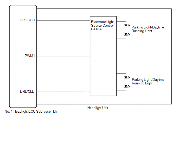
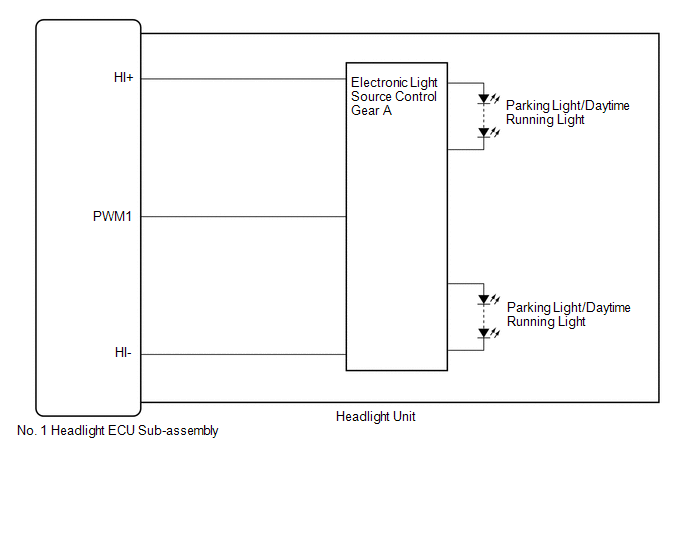
WIRING DIAGRAM
for Multiple Beam Headlight
for Single Beam Headlight
CAUTION / NOTICE / HINT
NOTICE:
-
If the No. 1 headlight ECU sub-assembly LH has been replaced, it is necessary to synchronize the vehicle information and initialize the No. 1 headlight ECU sub-assembly LH.
Click here
.gif)
-
If the headlight assembly LH has been replaced, it is necessary to synchronize the vehicle information and initialize the No. 1 headlight ECU sub-assembly LH.*
Click here
- When replacing the No. 1 headlight ECU sub-assembly LH, always replace it with a new one. If a No. 1 headlight ECU sub-assembly LH which was installed to another vehicle is used, the information stored in it will not match the information from the vehicle and a DTC may be stored.
-
When replacing the headlight assembly LH, always replace it with a new one. If a headlight assembly LH which was installed to another vehicle is used, the information stored in it will not match the information from the vehicle and a DTC may be stored.*
- *: for TMMC Made
PROCEDURE
| 1. | CONFIRM MODEL |
(a) Choose the model to be inspected.
| Result | Proceed to |
|---|---|
| for Multiple Beam Headlight | A |
| for Single Beam Headlight | B |
| B | .gif) | GO TO STEP 3 |
|
.gif)
| 2. | PERFORM ACTIVE TEST USING TECHSTREAM |
(a) Connect the Techstream to the DLC3.
(b) Turn the engine switch on (IG).
(c) Turn the Techstream on.
(d) Enter the following menus: Body Electrical / AFS / Active Test.
(e) Perform the Active Test according to the display on the Techstream.
Body Electrical > AFS > Active Test| Tester Display | Measurement Item | Control Range | Diagnostic Note |
|---|---|---|---|
| Clearance Light | Parking lights | OFF or ON | - |
| Daytime Running Light | Daytime running lights | OFF or ON | This Active Test can only be performed when the customization item DRL function is set to "ON" using the Techstream. |
| Tester Display |
|---|
| Clearance Light |
| Tester Display |
|---|
| Daytime Running Light |
OK:
Parking lights and daytime running lights illuminate.
| Result | Proceed to |
|---|---|
| OK | A |
| NG (LH side parking light and daytime running light does not illuminate) | B |
| NG (RH side parking light and daytime running light does not illuminate) | C |
| A | | PROCEED TO NEXT SUSPECTED AREA SHOWN IN PROBLEM SYMPTOMS TABLE |
| B | | GO TO STEP 4 |
| C | | GO TO STEP 6 |
| 3. | PERFORM ACTIVE TEST USING TECHSTREAM |
(a) Connect the Techstream to the DLC3.
(b) Turn the engine switch on (IG).
(c) Turn the Techstream on.
(d) Enter the following menus: Body Electrical / HL AutoLeveling / Active Test.
(e) Perform the Active Test according to the display on the Techstream.
Body Electrical > HL AutoLeveling > Active Test| Tester Display | Measurement Item | Control Range | Diagnostic Note |
|---|---|---|---|
| Clearance Light | Parking lights | OFF or ON | - |
| Daytime Running Light | Daytime running lights | OFF or ON | This Active Test can only be performed when the customization item DRL function is set to "ON" using the Techstream. |
| Tester Display |
|---|
| Clearance Light |
| Tester Display |
|---|
| Daytime Running Light |
OK:
Parking lights and daytime running lights illuminate.
| Result | Proceed to |
|---|---|
| OK | A |
| NG (LH side parking light and daytime running light does not illuminate) | B |
| NG (RH side parking light and daytime running light does not illuminate) | C |
| A | | PROCEED TO NEXT SUSPECTED AREA SHOWN IN PROBLEM SYMPTOMS TABLE |
| C | | GO TO STEP 6 |
|
| 4. | CHECK HEADLIGHT UNIT LH |
(a) Interchange the headlight unit LH with RH and connect the connectors.
Click here
|
| 5. | CHECK OPERATION (PARKING LIGHTS AND DAYTIME RUNNING LIGHTS) |
(a) Check the operation of the parking lights and daytime running lights.
OK:
The parking lights and daytime running lights operate normally.
| Result | Proceed to |
|---|---|
| OK | A |
| NG (for TMC Made) | B |
| NG (for TMMC Made) | C |
| A | | REPLACE NO. 1 HEADLIGHT ECU SUB-ASSEMBLY LH |
| B | | REPLACE HEADLIGHT UNIT LH |
| C | | REPLACE HEADLIGHT ASSEMBLY LH |
| 6. | CHECK HEADLIGHT UNIT RH |
(a) Interchange the headlight unit RH with LH and connect the connectors.
Click here
|
| 7. | CHECK OPERATION (PARKING LIGHTS AND DAYTIME RUNNING LIGHTS) |
(a) Check the operation of the parking lights and daytime running lights.
OK:
The parking lights and daytime running lights operate normally.
| Result | Proceed to |
|---|---|
| OK | A |
| NG (for TMC Made) | B |
| NG (for TMMC Made) | C |
| A | | REPLACE NO. 1 HEADLIGHT ECU SUB-ASSEMBLY RH |
| B | | REPLACE HEADLIGHT UNIT RH |
| C | | REPLACE HEADLIGHT ASSEMBLY RH |
 Headlight Dimmer Switch Circuit
DESCRIPTION The main body ECU (multiplex network body ECU) receives the following switch information:
Light control switch in DRL OFF*1, tail, head, AUTO position
Dimmer switch in high, low or hi ...
 Front Fog Light Circuit
DESCRIPTION The main body ECU (multiplex network body ECU) controls the front fog lights. WIRING DIAGRAM CAUTION / NOTICE / HINT NOTICE:
Inspect the fuses for circuits related to this system befor ...
Other materials:
Lexus RX (RX 350L, RX450h) 2016-2026 Repair Manual > Smart Access System With Push-button Start (for Start Function): Dtc Check / Clear
DTC CHECK / CLEAR NOTICE: When using the Techstream with the engine switch off, connect the Techstream to the DLC3 and turn a courtesy light switch on and off at intervals of 1.5 seconds or less until communication between the Techstream and the vehicle begins. Then select the vehicle type under man ...
Lexus RX (RX 350L, RX450h) 2016-2026 Repair Manual > Rear Power Seat Control System(for Third Row): Back Door Courtesy Switch Circuit
DESCRIPTION Each fold seat control ECU receives back door courtesy light switch input signal to determine the state of the back door and enable or disable the fold and return functions. WIRING DIAGRAM CAUTION / NOTICE / HINT NOTICE:
When a fold seat control ECU (RH/LH seat) is replaced, it is ne ...
Lexus RX (RX 350L, RX450h) 2016-{YEAR} Owners Manual
- For your information
- Pictorial index
- For safety and security
- Instrument cluster
- Operation of each component
- Driving
- Lexus Display Audio system
- Interior features
- Maintenance and care
- When trouble arises
- Vehicle specifications
- For owners
Lexus RX (RX 350L, RX450h) 2016-{YEAR} Repair Manual

0.0119