Lexus RX (RX 350L, RX450h) 2016-2026 Repair Manual: Headlight Dimmer Switch Circuit
DESCRIPTION
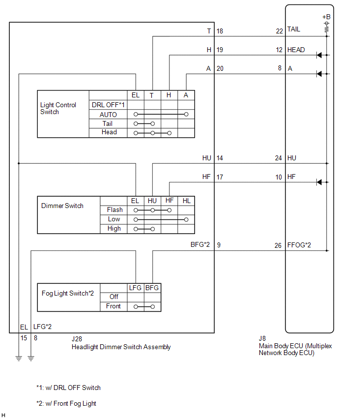
The main body ECU (multiplex network body ECU) receives the following switch information:
- Light control switch in DRL OFF*1, tail, head, AUTO position
- Dimmer switch in high, low or high flash (pass) position
- Fog light switch in front or off position*2
- *1: w/ DRL OFF Switch
- *2: w/ Front Fog Light
WIRING DIAGRAM
CAUTION / NOTICE / HINT
NOTICE:
Before replacing the main body ECU (multiplex network body ECU), refer to Registration.
Click here .gif)
PROCEDURE
| 1. | READ VALUE USING TECHSTREAM |
(a) Connect the Techstream to the DLC3.
(b) Turn the engine switch on (IG).
(c) Turn the Techstream on.
(d) Enter the following menus: Body Electrical / Main Body / Data List.
(e) Read the Data List according to the display on the Techstream.
Body Electrical > Main Body > Data List| Tester Display | Measurement Item | Range | Normal Condition | Diagnostic Note |
|---|---|---|---|---|
| Dimmer SW | Dimmer switch high position signal | OFF or ON | OFF: Dimmer switch in low position ON: Dimmer switch in high or high flash position | - |
| Passing Light SW | Dimmer switch high flash position (pass) signal | OFF or ON | OFF: Dimmer switch not in high flash position ON: Dimmer switch in high flash position | - |
| Front Fog Light SW | Fog light switch front position signal | OFF or ON | OFF: Fog light switch off ON: Fog light switch in front position |
|
| Auto Light SW | Light control switch AUTO position signal | OFF or ON | OFF: Light control switch not in AUTO position ON: Light control switch in AUTO position | - |
| Head Light SW (Head) | Light control switch head position signal | OFF or ON | OFF: Light control switch not in head position ON: Light control switch in head position | - |
| Head Light SW (Tail) | Light control switch tail position signal | OFF or ON | OFF: Light control switch not in tail or head position ON: Light control switch in tail or head position | - |
| Tester Display |
|---|
| Dimmer SW |
| Passing Light SW |
| Front Fog Light SW |
| Auto Light SW |
| Head Light SW (Head) |
| Head Light SW (Tail) |
OK:
Normal conditions listed above are displayed.
| OK | .gif) | PROCEED TO NEXT SUSPECTED AREA SHOWN IN PROBLEM SYMPTOMS TABLE |
|
.gif)
| 2. | INSPECT HEADLIGHT DIMMER SWITCH ASSEMBLY |
(a) Remove the headlight dimmer switch assembly.
Click here
(b) Inspect the headlight dimmer switch assembly.
Click here
| NG | | REPLACE HEADLIGHT DIMMER SWITCH ASSEMBLY |
|
| 3. | CHECK HARNESS AND CONNECTOR (HEADLIGHT DIMMER SWITCH ASSEMBLY - MAIN BODY ECU (MULTIPLEX NETWORK BODY ECU) AND BODY GROUND) |
(a) Disconnect the J8 main body ECU (multiplex network body ECU) connector.
(b) Measure the resistance according to the value(s) in the table below.
Standard Resistance:
| Tester Connection | Condition | Specified Condition |
|---|---|---|
| J28-18 (T) - J8-22 (TAIL) | Always | Below 1 Ω |
| J28-19 (H) - J8-12 (HEAD) | Always | Below 1 Ω |
| J28-20 (A) - J8-8 (A) | Always | Below 1 Ω |
| J28-14 (HU) - J8-24 (HU) | Always | Below 1 Ω |
| J28-17 (HF) - J8-10 (HF) | Always | Below 1 Ω |
| J28-9 (BFG) - J8-26 (FFOG)* | Always | Below 1 Ω |
| J28-18 (T) or J8-22 (TAIL) - Body ground | Always | 10 kΩ or higher |
| J28-19 (H) or J8-12 (HEAD) - Body ground | Always | 10 kΩ or higher |
| J28-20 (A) or J8-8 (A) - Body ground | Always | 10 kΩ or higher |
| J28-14 (HU) or J8-24 (HU) - Body ground | Always | 10 kΩ or higher |
| J28-17 (HF) or J8-10 (HF) - Body ground | Always | 10 kΩ or higher |
| J28-9 (BFG) or J8-26 (FFOG) - Body ground* | Always | 10 kΩ or higher |
| J28-8 (LFG) - Body ground | Always | Below 1 Ω |
| J28-15 (EL) - Body ground | Always | Below 1 Ω |
- *: w/ Front Fog Light
| OK | | REPLACE MAIN BODY ECU (MULTIPLEX NETWORK BODY ECU) |
| NG | | REPAIR OR REPLACE HARNESS OR CONNECTOR |
 Automatic High Beam System does not Operate or Operation Indicator does not Illuminate
DESCRIPTION The main body ECU (multiplex network body ECU) controls the automatic high beam system based on signals received from the forward recognition camera. WIRING DIAGRAM CAUTION / NOTICE / HIN ...
 Parking Light/Daytime Running Light Circuit
DESCRIPTION Parking light function:
When the main body ECU (multiplex network body ECU) receives the light control switch position signal, it sends an illumination request signal to the No. 1 headl ...
Other materials:
Lexus RX (RX 350L, RX450h) 2016-2026 Repair Manual > Oil Pressure Switch: Installation
INSTALLATION PROCEDURE 1. INSTALL ENGINE OIL PRESSURE SWITCH ASSEMBLY (a) Apply adhesive to 2 or 3 threads of the engine oil pressure switch assembly. Adhesive: Toyota Genuine Adhesive 1344, Three Bond 1344 or equivalent NOTICE:
Do not apply adhesive to the oil inlet port of the engine oil ...
Lexus RX (RX 350L, RX450h) 2016-2026 Repair Manual > Automatic Transaxle System: Transmission Fluid Temperature Sensor "A" Circuit Short to Battery or Open (P071015)
DESCRIPTION The ATF temperature sensor converts the automatic transaxle fluid (ATF) temperature into a resistance value for use by the ECM. The ECM applies voltage to the temperature sensor through terminal THO1 of the ECM. The sensor resistance changes with the ATF temperature. As the temperature r ...
Lexus RX (RX 350L, RX450h) 2016-{YEAR} Owners Manual
- For your information
- Pictorial index
- For safety and security
- Instrument cluster
- Operation of each component
- Driving
- Lexus Display Audio system
- Interior features
- Maintenance and care
- When trouble arises
- Vehicle specifications
- For owners
Lexus RX (RX 350L, RX450h) 2016-{YEAR} Repair Manual

0.0111