Lexus RX (RX 350L, RX450h) 2016-2026 Repair Manual: P/W Master Switch Communication Stop (B1206)
DESCRIPTION
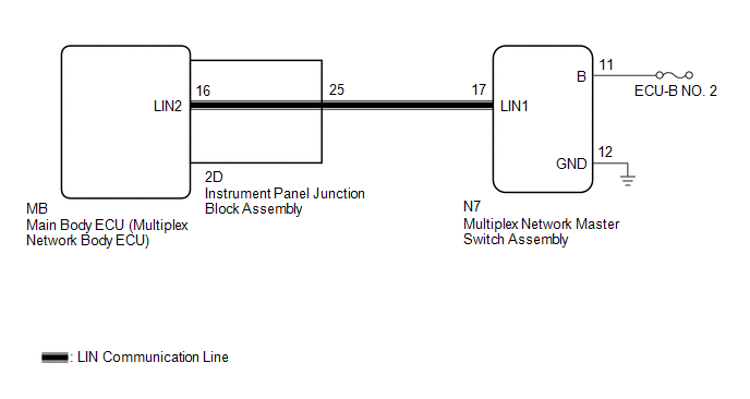
This DTC is stored when LIN communication between the multiplex network master switch assembly and main body ECU (multiplex network body ECU) stops for 10 seconds or more.
| DTC No. | Detection Item | DTC Detection Condition | Trouble Area |
|---|---|---|---|
| B1206 | P/W Master Switch Communication Stop | No communication between multiplex network master switch assembly and main body ECU (multiplex network body ECU) for 10 seconds or more. |
|
WIRING DIAGRAM
CAUTION / NOTICE / HINT
NOTICE:
- Inspect the fuses for circuits related to this system before performing the following procedure.
-
Before replacing the main body ECU (multiplex network body ECU), refer to Registration.
Click here
.gif)
PROCEDURE
| 1. | INSPECT INSTRUMENT PANEL JUNCTION BLOCK ASSEMBLY |
(a) Remove the instrument panel junction block assembly.
Click here
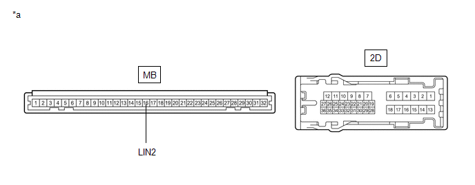
| *a | Component without harness connected (Instrument Panel Junction Block Assembly) | - | - |
(b) Remove the main body ECU (multiplex network body ECU) from the instrument panel junction block assembly.
(c) Measure the resistance according to the value(s) in the table below.
HINT:
This inspection is to check the LIN communication line in the instrument panel junction block assembly that connects the wire harness to the built-in main body ECU (multiplex network body ECU).
Standard Resistance:
| Tester Connection | Condition | Specified Condition |
|---|---|---|
| 2D-25 - MB-16 (LIN2) | Always | Below 1 Ω |
| NG | .gif) | REPLACE INSTRUMENT PANEL JUNCTION BLOCK ASSEMBLY |
|
.gif)
| 2. | CHECK HARNESS AND CONNECTOR (INSTRUMENT PANEL JUNCTION BLOCK ASSEMBLY - MULTIPLEX NETWORK MASTER SWITCH ASSEMBLY) |
(a) Disconnect the N7 multiplex network master switch assembly connector.
(b) Measure the resistance according to the value(s) in the table below.
NOTICE:
Make sure that each ECU is in sleep mode before performing the inspection. To enter sleep mode, turn the engine switch from on (IG) to off and wait for 180 seconds or more without operating any switches.
Standard Resistance:
| Tester Connection | Condition | Specified Condition |
|---|---|---|
| 2D-25 - N7-17 (LIN1) | Engine switch off | Below 1 Ω |
| N7-17 (LIN1) or 2D-25 - Body ground | Engine switch off | 10 kΩ or higher |
| NG | | REPAIR OR REPLACE HARNESS OR CONNECTOR |
|
| 3. | CHECK HARNESS AND CONNECTOR (MULTIPLEX NETWORK MASTER SWITCH ASSEMBLY - BATTERY, BODY GROUND) |
(a) Measure the voltage according to the value(s) in the table below.
Standard Voltage:
| Tester Connection | Condition | Specified Condition |
|---|---|---|
| N7-11 (B) - N7-12 (E) | Always | 11 to 14 V |
(b) Measure the resistance according to the value(s) in the table below.
Standard Resistance:
| Tester Connection | Condition | Specified Condition |
|---|---|---|
| N7-12 (GND) - Body ground | Always | Below 1 Ω |
| NG | | REPAIR OR REPLACE HARNESS OR CONNECTOR |
|
| 4. | REPLACE MULTIPLEX NETWORK MASTER SWITCH ASSEMBLY |
(a) Replace the multiplex network master switch assembly.
Click here
|
| 5. | CHECK FOR DTC |
(a) Clear the DTCs.
Click here
(b) Recheck for DTCs.
Body Electrical > Main Body > Trouble CodesOK:
DTC B1206 is not output.
| OK | | END (MULTIPLEX NETWORK MASTER SWITCH ASSEMBLY WAS DEFECTIVE) |
| NG | | REPLACE MAIN BODY ECU (MULTIPLEX NETWORK BODY ECU) |
 Dtc Check / Clear
DTC CHECK / CLEAR CHECK DTC (a) Connect the Techstream to the DLC3. (b) Turn the engine switch on (IG). (c) Turn the Techstream on. (d) Enter the following menus: Body Electrical / Main Body or Smart ...
 Driver Side Door ECU Communication Stop (B2321)
DESCRIPTION This DTC is stored when LIN communication between the power window regulator motor assembly LH and main body ECU (multiplex network body ECU) stops for 10 seconds or more. DTC No. Det ...
Other materials:
Lexus RX (RX 350L, RX450h) 2016-2026 Repair Manual > Electric Parking Brake System: Test Mode Procedure
TEST MODE PROCEDURE REAR BRAKE PAD REPLACEMENT MODE *1 Rear Disc Brake Piston *2 Nut *a The nut moves inward in pad replacement mode HINT: When replacing the rear disc brake pad and rear disc, since the nut inside the rear disc brake cylinder assembly is in an advanced position, ...
Lexus RX (RX 350L, RX450h) 2016-2026 Repair Manual > Power Steering System: How To Proceed With Troubleshooting
CAUTION / NOTICE / HINT HINT:
Use these procedures to troubleshoot the power steering system.
*: Use the Techstream.
PROCEDURE 1. VEHICLE BROUGHT TO WORKSHOP
NEXT 2. INSPECT BATTERY VOLTAGE (a) Turn the engine switch off. (b) Measure the voltage of the batt ...
Lexus RX (RX 350L, RX450h) 2016-{YEAR} Owners Manual
- For your information
- Pictorial index
- For safety and security
- Instrument cluster
- Operation of each component
- Driving
- Lexus Display Audio system
- Interior features
- Maintenance and care
- When trouble arises
- Vehicle specifications
- For owners
Lexus RX (RX 350L, RX450h) 2016-{YEAR} Repair Manual

0.0096