Lexus RX (RX 350L, RX450h) 2016-2026 Repair Manual: Lost Communication with Haptic Device (B1323-B1326)
DESCRIPTION
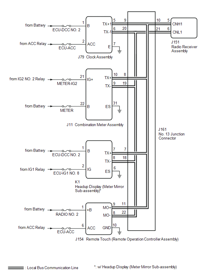
These DTCs are stored when communication between the radio receiver assembly and remote touch (remote operation controller assembly), combination meter assembly, headup display (meter mirror sub-assembly)* or clock assembly is not possible.
- *: w/ Headup Display System
| DTC No. | Detection Item | DTC Detection Condition | Trouble Area |
|---|---|---|---|
| B1323 | Lost Communication with Haptic Device | CAN reception error |
|
| B1324 | Lost Communication with Meter | CAN reception error |
|
| B1325 | Lost Communication with HUD | CAN reception error |
|
| B1326 | Lost Communication with Clock Device (Local-CAN) | CAN reception error |
|
HINT:
The radio receiver assembly is the master unit.
WIRING DIAGRAM
CAUTION / NOTICE / HINT
NOTICE:
-
Depending on the parts that are replaced during vehicle inspection or maintenance, performing initialization, registration or calibration may be needed. Refer to Precaution for Audio and Visual System.
Click here
.gif)
- Inspect the fuses for circuits related to this system before performing the following procedure.
PROCEDURE
| 1. | CHECK DTC |
(a) Check for DTCs.
Body Electrical > Navigation System > Trouble Codes| Result | Proceed to |
|---|---|
| DTC B1323, B1324, B1325* and B1326 are not output | A |
| DTC B1323, B1324, B1325* and B1326 are output | B |
| DTC B1323 is output | C |
| DTC B1324 is output | D |
| DTC B1325 is output | E |
| DTC B1326 is output | F |
| A |  | USE SIMULATION METHOD TO CHECK |
| C | | GO TO STEP 17 |
| D | | GO TO STEP 19 |
| E | | GO TO STEP 21 |
| F | | GO TO STEP 23 |
|

| 2. | CHECK LOCAL BUS |
(a) Disconnect the cable from the negative (-) battery terminal.
(b) Measure the resistance according to the value(s) in the table below.
Standard Resistance:
| Tester Connection | Condition | Specified Condition |
|---|---|---|
| J161-10 - J161-21 | Cable disconnected from negative (-) battery terminal | 54 to 69 Ω |
| Result | Proceed to |
|---|---|
| OK | A |
| NG (Below 54 Ω) | B |
| NG (70 Ω or higher) | C |
| A | | USE SIMULATION METHOD TO CHECK |
| C | | GO TO STEP 13 |
|
| 3. | CHECK HARNESS AND CONNECTOR (NO. 13 JUNCTION CONNECTOR - RADIO RECEIVER ASSEMBLY) |
(a) Disconnect the cable from the negative (-) battery terminal.
(b) Disconnect the J161 No. 13 junction connector.
(c) Connect the J151 radio receiver assembly connector.
(d) Measure the resistance according to the value(s) in the table below.
Standard Resistance:
| Tester Connection | Condition | Specified Condition |
|---|---|---|
| J161-10 - J161-21 | Cable disconnected from negative (-) battery terminal | 108 to 132 Ω |
| NG | | GO TO STEP 12 |
|
| 4. | CHECK HARNESS AND CONNECTOR (NO. 13 JUNCTION CONNECTOR - REMOTE TOUCH (REMOTE OPERATION CONTROLLER ASSEMBLY)) |
(a) Disconnect the cable from the negative (-) battery terminal.
(b) Disconnect the J161 No. 13 junction connector.
(c) Connect the J154 remote touch (remote operation controller assembly) connector.
(d) Measure the resistance according to the value(s) in the table below.
Standard Resistance:
| Tester Connection | Condition | Specified Condition |
|---|---|---|
| J161-11 - J161-22 | Cable disconnected from negative (-) battery terminal | 108 to 132 Ω |
| NG | | GO TO STEP 11 |
|
| 5. | CHECK HARNESS AND CONNECTOR (NO. 13 JUNCTION CONNECTOR - COMBINATION METER ASSEMBLY) |
(a) Disconnect the cable from the negative (-) battery terminal.
(b) Disconnect the J161 No. 13 junction connector.
(c) Connect the J11 combination meter assembly connector.
(d) Measure the resistance according to the value(s) in the table below.
Standard Resistance:
| Tester Connection | Condition | Specified Condition |
|---|---|---|
| J161-8 - J161-19 | Cable disconnected from negative (-) battery terminal | 200 Ω or higher |
| NG | | GO TO STEP 10 |
|
| 6. | CHECK HARNESS AND CONNECTOR (NO. 13 JUNCTION CONNECTOR - CLOCK ASSEMBLY) |
(a) Disconnect the cable from the negative (-) battery terminal.
(b) Disconnect the J161 No. 13 junction connector.
(c) Connect the J79 clock assembly connector.
(d) Measure the resistance according to the value(s) in the table below.
Standard Resistance:
| Tester Connection | Condition | Specified Condition |
|---|---|---|
| J161-9 - J161-20 | Cable disconnected from negative (-) battery terminal | 200 Ω or higher |
| Result | Proceed to |
|---|---|
| OK (w/o Headup Display System) | A |
| OK (w/ Headup Display System) | B |
| NG | C |
| A | | REPLACE NO. 13 CAN JUNCTION CONNECTOR |
| C | | GO TO STEP 9 |
|
| 7. | CHECK HARNESS AND CONNECTOR (NO. 13 JUNCTION CONNECTOR - HEADUP DISPLAY (METER MIRROR SUB-ASSEMBLY)) |
(a) Disconnect the cable from the negative (-) battery terminal.
(b) Disconnect the J161 No. 13 junction connector.
(c) Connect the K1 headup display (meter mirror sub-assembly) connector.
(d) Measure the resistance according to the value(s) in the table below.
Standard Resistance:
| Tester Connection | Condition | Specified Condition |
|---|---|---|
| J161-7 - J161-18 | Cable disconnected from negative (-) battery terminal | 200 Ω or higher |
| OK | | REPLACE NO. 13 CAN JUNCTION CONNECTOR |
|
| 8. | CHECK HARNESS AND CONNECTOR (HEADUP DISPLAY (METER MIRROR SUB-ASSEMBLY) - NO. 13 JUNCTION CONNECTOR) |
(a) Disconnect the cable from the negative (-) battery terminal.
(b) Disconnect the K1 headup display (meter mirror sub-assembly) connector.
(c) Connect the J161 No. 13 junction connector.
(d) Measure the resistance according to the value(s) in the table below.
Standard Resistance:
| Tester Connection | Condition | Specified Condition |
|---|---|---|
| K1-7 (TX+) - K1-8 (TX-) | Cable disconnected from negative (-) battery terminal | 54 to 69 Ω |
| OK | | REPLACE HEADUP DISPLAY (METER MIRROR SUB-ASSEMBLY) |
| NG | | REPAIR OR REPLACE HARNESS OR CONNECTOR |
| 9. | CHECK HARNESS AND CONNECTOR (CLOCK ASSEMBLY - NO. 13 JUNCTION CONNECTOR) |
(a) Disconnect the cable from the negative (-) battery terminal.
(b) Disconnect the J79 clock assembly connector.
(c) Connect the J161 No. 13 junction connector.
(d) Measure the resistance according to the value(s) in the table below.
Standard Resistance:
| Tester Connection | Condition | Specified Condition |
|---|---|---|
| J79-5 (TX+1) - J79-6 (TX-1) | Cable disconnected from negative (-) battery terminal | 54 to 69 Ω |
| OK | | REPLACE CLOCK ASSEMBLY |
| NG | | REPAIR OR REPLACE HARNESS OR CONNECTOR |
| 10. | CHECK HARNESS AND CONNECTOR (COMBINATION METER ASSEMBLY - NO. 13 JUNCTION CONNECTOR) |
(a) Disconnect the cable from the negative (-) battery terminal.
(b) Disconnect the J11 combination meter assembly connector.
(c) Connect the J161 No. 13 junction connector.
(d) Measure the resistance according to the value(s) in the table below.
Standard Resistance:
| Tester Connection | Condition | Specified Condition |
|---|---|---|
| J11-10 (TX+) - J11-9 (TX-) | Cable disconnected from negative (-) battery terminal | 54 to 69 Ω |
| OK | | REPLACE COMBINATION METER ASSEMBLY |
| NG | | REPAIR OR REPLACE HARNESS OR CONNECTOR |
| 11. | CHECK HARNESS AND CONNECTOR (REMOTE TOUCH (REMOTE OPERATION CONTROLLER ASSEMBLY) - NO. 13 JUNCTION CONNECTOR) |
(a) Disconnect the cable from the negative (-) battery terminal.
(b) Disconnect the J154 remote touch (remote operation controller assembly) connector.
(c) Connect the J161 No. 13 junction connector.
(d) Measure the resistance according to the value(s) in the table below.
Standard Resistance:
| Tester Connection | Condition | Specified Condition |
|---|---|---|
| J154-9 (MO+) - J154-8 (MO-) | Cable disconnected from negative (-) battery terminal | 108 to 132 Ω |
| OK | | REPLACE REMOTE TOUCH (REMOTE OPERATION CONTROLLER ASSEMBLY) |
| NG | | REPAIR OR REPLACE HARNESS OR CONNECTOR |
| 12. | CHECK HARNESS AND CONNECTOR (RADIO RECEIVER ASSEMBLY - NO. 13 JUNCTION CONNECTOR) |
(a) Disconnect the cable from the negative (-) battery terminal.
(b) Disconnect the J151 radio receiver assembly connector.
(c) Connect the J161 No. 13 junction connector.
(d) Measure the resistance according to the value(s) in the table below.
Standard Resistance:
| Tester Connection | Condition | Specified Condition |
|---|---|---|
| J151-5 (CNH1) - J151-6 (CNL1) | Cable disconnected from negative (-) battery terminal | 108 to 132 Ω |
| OK | | REPLACE RADIO RECEIVER ASSEMBLY |
| NG | | REPAIR OR REPLACE HARNESS OR CONNECTOR |
| 13. | CHECK HARNESS AND CONNECTOR (NO. 13 JUNCTION CONNECTOR - RADIO RECEIVER ASSEMBLY) |
(a) Disconnect the cable from the negative (-) battery terminal.
(b) Disconnect the J161 No. 13 junction connector.
(c) Connect the J151 radio receiver assembly connector.
(d) Measure the resistance according to the value(s) in the table below.
Standard Resistance:
| Tester Connection | Condition | Specified Condition |
|---|---|---|
| J161-10 - J161-21 | Cable disconnected from negative (-) battery terminal | 108 to 132 Ω |
| NG | | GO TO STEP 16 |
|
| 14. | CHECK HARNESS AND CONNECTOR (NO. 13 JUNCTION CONNECTOR - REMOTE TOUCH (REMOTE OPERATION CONTROLLER ASSEMBLY)) |
(a) Disconnect the cable from the negative (-) battery terminal.
(b) Disconnect the J161 No. 13 junction connector.
(c) Connect the J154 remote touch (remote operation controller assembly) connector.
(d) Measure the resistance according to the value(s) in the table below.
Standard Resistance:
| Tester Connection | Condition | Specified Condition |
|---|---|---|
| J161-11 - J161-22 | Cable disconnected from negative (-) battery terminal | 108 to 132 Ω |
| OK | | REPLACE NO. 17 JUNCTION CONNECTOR |
|
| 15. | CHECK HARNESS AND CONNECTOR (REMOTE TOUCH (REMOTE OPERATION CONTROLLER ASSEMBLY) - NO. 13 JUNCTION CONNECTOR) |
(a) Disconnect the cable from the negative (-) battery terminal.
(b) Disconnect the J154 remote touch (remote operation controller assembly) connector.
(c) Connect the J161 No. 13 junction connector.
(d) Measure the resistance according to the value(s) in the table below.
Standard Resistance:
| Tester Connection | Condition | Specified Condition |
|---|---|---|
| J154-9 (MO+) - J154-8 (MO-) | Cable disconnected from negative (-) battery terminal | 108 to 132 Ω |
| OK | | REPLACE REMOTE TOUCH (REMOTE OPERATION CONTROLLER ASSEMBLY) |
| NG | | REPAIR OR REPLACE HARNESS OR CONNECTOR |
| 16. | CHECK HARNESS AND CONNECTOR (RADIO RECEIVER ASSEMBLY - NO. 13 JUNCTION CONNECTOR) |
(a) Disconnect the cable from the negative (-) battery terminal.
(b) Disconnect the J151 radio receiver assembly connector.
(c) Connect the J161 No. 13 junction connector.
(d) Measure the resistance according to the value(s) in the table below.
Standard Resistance:
| Tester Connection | Condition | Specified Condition |
|---|---|---|
| J151-5 (CNH1) - J151-6 (CNL1) | Cable disconnected from negative (-) battery terminal | 108 to 132 Ω |
| OK | | REPLACE RADIO RECEIVER ASSEMBLY |
| NG | | REPAIR OR REPLACE HARNESS OR CONNECTOR |
| 17. | CHECK HARNESS AND CONNECTOR (REMOTE TOUCH (REMOTE OPERATION CONTROLLER ASSEMBLY) POWER SOURCE) |
(a) Disconnect the J154 remote touch (remote operation controller assembly) connector.
(b) Measure the resistance according to the value(s) in the table below.
Standard Resistance:
| Tester Connection | Condition | Specified Condition |
|---|---|---|
| J154-10 (GND) - Body ground | Always | Below 1 Ω |
(c) Measure the voltage according to the value(s) in the table below.
Standard Voltage:
| Tester Connection | Condition | Specified Condition |
|---|---|---|
| J154-1 (+B) - Body ground | Always | 11 to 14 V |
| J154-6 (ACC) - Body ground | Engine switch on (ACC) | 11 to 14 V |
| NG | | REPAIR OR REPLACE HARNESS OR CONNECTOR |
|
| 18. | CHECK HARNESS AND CONNECTOR (REMOTE TOUCH (REMOTE OPERATION CONTROLLER ASSEMBLY) - NO. 13 JUNCTION CONNECTOR) |
(a) Disconnect the cable from the negative (-) battery terminal.
(b) Disconnect the J154 remote touch (remote operation controller assembly) connector.
(c) Connect the J161 No. 13 junction connector.
(d) Measure the resistance according to the value(s) in the table below.
Standard Resistance:
| Tester Connection | Condition | Specified Condition |
|---|---|---|
| J154-9 (MO+) - J154-8 (MO-) | Cable disconnected from negative (-) battery terminal | 108 to 132 Ω |
| OK | | REPLACE REMOTE TOUCH (REMOTE OPERATION CONTROLLER ASSEMBLY) |
| NG | | REPAIR OR REPLACE HARNESS OR CONNECTOR |
| 19. | CHECK HARNESS AND CONNECTOR (COMBINATION METER ASSEMBLY POWER SOURCE) |
(a) Disconnect the J11 combination meter assembly connector.
(b) Measure the resistance according to the value(s) in the table below.
Standard Resistance:
| Tester Connection | Condition | Specified Condition |
|---|---|---|
| J11-31 (ES) - Body ground | Always | Below 1 Ω |
(c) Measure the voltage according to the value(s) in the table below.
Standard Voltage:
| Tester Connection | Condition | Specified Condition |
|---|---|---|
| J11-22 (B) - Body ground | Always | 11 to 14 V |
| J11-21 (IG+) - Body ground | Engine switch on (IG) | 11 to 14 V |
| NG | | REPAIR OR REPLACE HARNESS OR CONNECTOR |
|
| 20. | CHECK HARNESS AND CONNECTOR (COMBINATION METER ASSEMBLY - NO. 13 JUNCTION CONNECTOR) |
(a) Disconnect the cable from the negative (-) battery terminal.
(b) Disconnect the J11 combination meter assembly connector.
(c) Connect the J161 No. 13 junction connector.
(d) Measure the resistance according to the value(s) in the table below.
Standard Resistance:
| Tester Connection | Condition | Specified Condition |
|---|---|---|
| J11-10 (TX+) - J11-9 (TX-) | Cable disconnected from negative (-) battery terminal | 54 to 69 Ω |
| OK | | REPLACE COMBINATION METER ASSEMBLY |
| NG | | REPAIR OR REPLACE HARNESS OR CONNECTOR |
| 21. | CHECK HARNESS AND CONNECTOR (HEADUP DISPLAY (METER MIRROR SUB-ASSEMBLY) POWER SOURCE) |
(a) Disconnect the K1 headup display (meter mirror sub-assembly) connector.
(b) Measure the resistance according to the value(s) in the table below.
Standard Resistance:
| Tester Connection | Condition | Specified Condition |
|---|---|---|
| K1-6 (ES) - Body ground | Always | Below 1 Ω |
(c) Measure the voltage according to the value(s) in the table below.
Standard Voltage:
| Tester Connection | Condition | Specified Condition |
|---|---|---|
| K1-1 (B) - Body ground | Always | 11 to 14 V |
| K1-2 (IG) - Body ground | Engine switch on (IG) | 11 to 14 V |
| NG | | REPAIR OR REPLACE HARNESS OR CONNECTOR |
|
| 22. | CHECK HARNESS AND CONNECTOR (HEADUP DISPLAY (METER MIRROR SUB-ASSEMBLY) - NO. 13 JUNCTION CONNECTOR) |
(a) Disconnect the cable from the negative (-) battery terminal.
(b) Disconnect the K1 headup display (meter mirror sub-assembly) connector.
(c) Connect the J161 No. 13 junction connector.
(d) Measure the resistance according to the value(s) in the table below.
Standard Resistance:
| Tester Connection | Condition | Specified Condition |
|---|---|---|
| K1-7 (TX+) - K1-8 (TX-) | Cable disconnected from negative (-) battery terminal | 54 to 69 Ω |
| OK | | REPLACE HEADUP DISPLAY (METER MIRROR SUB-ASSEMBLY) |
| NG | | REPAIR OR REPLACE HARNESS OR CONNECTOR |
| 23. | CHECK HARNESS AND CONNECTOR (CLOCK ASSEMBLY POWER SOURCE) |
(a) Disconnect the J79 clock assembly connector.
(b) Measure the resistance according to the value(s) in the table below.
Standard Resistance:
| Tester Connection | Condition | Specified Condition |
|---|---|---|
| J79-7 (E) - Body ground | Always | Below 1 Ω |
(c) Measure the voltage according to the value(s) in the table below.
Standard Voltage:
| Tester Connection | Condition | Specified Condition |
|---|---|---|
| J79-1 (B) - Body ground | Always | 11 to 14 V |
| J79-2 (ACC) - Body ground | Engine switch on (ACC) | 11 to 14 V |
| NG | | REPAIR OR REPLACE HARNESS OR CONNECTOR |
|
| 24. | CHECK HARNESS AND CONNECTOR (CLOCK ASSEMBLY - NO. 13 JUNCTION CONNECTOR) |
(a) Disconnect the cable from the negative (-) battery terminal.
(b) Disconnect the J79 clock assembly connector.
(c) Connect the J161 No. 13 junction connector.
(d) Measure the resistance according to the value(s) in the table below.
Standard Resistance:
| Tester Connection | Condition | Specified Condition |
|---|---|---|
| J79-5 (TX+1) - J79-6 (TX-1) | Cable disconnected from negative (-) battery terminal | 54 to 69 Ω |
| OK | | REPLACE CLOCK ASSEMBLY |
| NG | | REPAIR OR REPLACE HARNESS OR CONNECTOR |
 Data List / Active Test
DATA LIST / ACTIVE TEST DATA LIST NOTICE: In the table below, the values listed under "Normal Condition" are reference values. Do not depend solely on these reference values when deciding whether a pa ...
 NTSC Disconnected (from Park Assist/Monitoring ECU) (B1535,C1622)
DESCRIPTION These DTCs are stored if the radio receiver assembly judges that the signals or signal lines between the rear television camera assembly and the multi-display assembly are not normal as a ...
Other materials:
Lexus RX (RX 350L, RX450h) 2016-2026 Repair Manual > Curtain Shield Airbag Assembly (w/o Rear No. 2 Seat): Removal
REMOVAL CAUTION / NOTICE / HINT The necessary procedures (adjustment, calibration, initialization, or registration) that must be performed after parts are removed, installed, or replaced during the curtain shield airbag assembly removal/installation are shown below. Necessary Procedure After Parts R ...
Lexus RX (RX 350L, RX450h) 2016-2026 Repair Manual > Vehicle Stability Control System: ECM Communication (C124A00)
DESCRIPTION DTC No. Detection Item DTC Detection Condition Trouble Area C124A00 ECM Communication Any of the following is detected:
The engine type, powertrain variation, engine stop and start ECU availability and destination information sent from the ECM do not match the informa ...
Lexus RX (RX 350L, RX450h) 2016-{YEAR} Owners Manual
- For your information
- Pictorial index
- For safety and security
- Instrument cluster
- Operation of each component
- Driving
- Lexus Display Audio system
- Interior features
- Maintenance and care
- When trouble arises
- Vehicle specifications
- For owners
Lexus RX (RX 350L, RX450h) 2016-{YEAR} Repair Manual

0.0121