Lexus RX (RX 350L, RX450h) 2016-2026 Repair Manual: On-vehicle Inspection
ON-VEHICLE INSPECTION
PROCEDURE
1. INSPECT SEMICONDUCTOR POWER INTEGRATION ECU (SIGNAL READING CHECK)
NOTICE:
Both present and history signal readings will be cleared if the semiconductor power integration ECU is removed. Make sure not to remove it before inspection.
HINT:
The signal readings of the semiconductor power integration ECU can be checked by inspecting the voltage at the diagnosis terminal.
(a) Signal reading check
(1) Turn the engine switch on (IG).
| (2) Connect the positive (+) terminal of a voltmeter to the semiconductor power integration ECU and the negative (-) terminal to the body ground. |
|
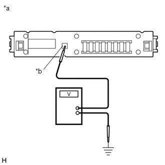
(3) Using the illustration below as a reference, determine whether any channels are malfunctioning based on the observed signal reading.
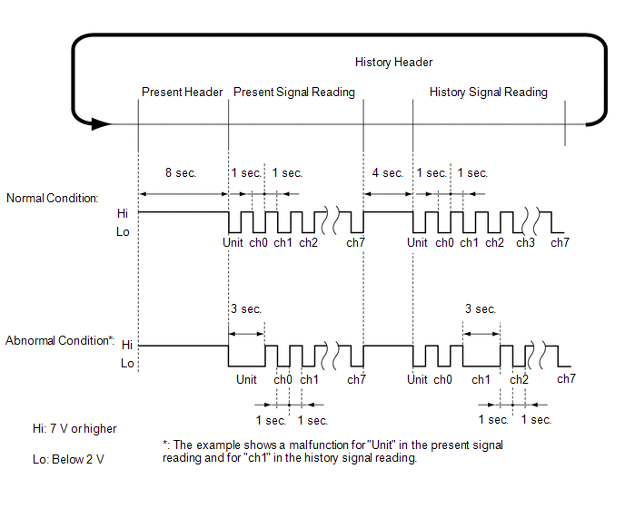
HINT:
- The present signal reading and history signal reading will be displayed alternately after the engine switch is turned on (IG). By measuring the duration of each header, the present signal reading and history signal reading can be recognized.
- A unit malfunction indicates an internal malfunction of the semiconductor power integration ECU. If a malfunction is detected for any channel from channel 0 to 7, an electrical load connected to the semiconductor power integration ECU may be malfunctioning or there may be a short in the semiconductor power integration ECU circuit or in the wire harness.
- The present signal reading will be stored as a history signal reading when electrical loads are operated after a malfunctioning part returns to normal.
- Both present and history signal readings can be cleared by disconnecting the cable from the negative (-) battery terminal.
-
Depending on the specification, different electrical loads connected to channels 0 to 7 are provided. Refer to the table below:
Channel
Connected Electrical Load
ch0
Cooler compressor assembly (Magnetic clutch assembly)
ch1
Rear window defogger wire
ch2
Windshield deicer wire*1
ch3
Front fog lights
ch4
Daytime running lights*2
ch5
Stop lights
ch6
High beam headlight RH*2
ch7
High beam headlight LH*2
- *1: w/ Windshield Deicer System
- *2: w/o Headlight Beam Level Control System
2. INSPECT SEMICONDUCTOR POWER INTEGRATION ECU (RESULTS OF SIGNAL READING CHECK)
(a) Results of signal reading check
(1) Depending on the signal reading, perform troubleshooting according to the table below.
| Output Signal Reading | Repair Method |
|---|---|
| Normal | Continue troubleshooting for each system. |
| The unit is malfunctioning | Replace the semiconductor power integration ECU. |
| A malfunction in a channel (ch0 to ch7) |
|
HINT:
Make sure to clear the signal readings by disconnecting the cable from the negative (-) battery terminal after replacement or repair of the malfunctioning part.
(2) If no signal readings are output, perform troubleshooting according to the following troubleshooting procedure.
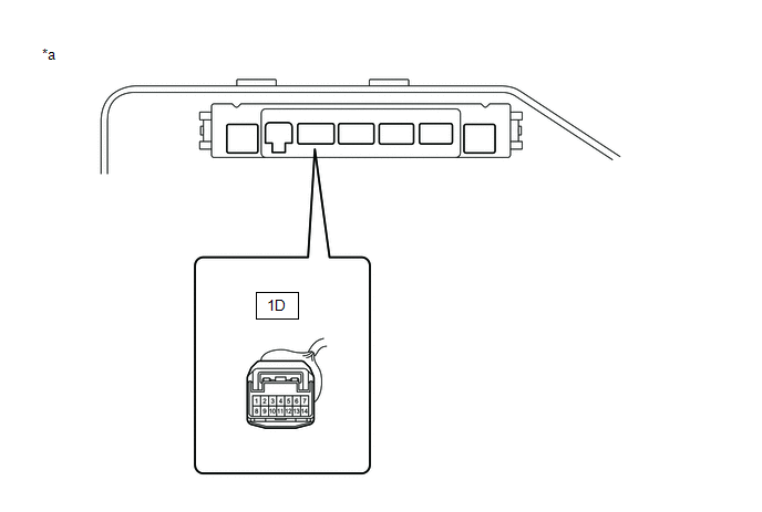
| *a | Component without semiconductor power integration ECU (No. 1 Engine Room Relay Block) | - | - |
-
Remove the semiconductor power integration ECU.
Click here
.gif)
-
Measure the voltage according to the value(s) in the table below.
Standard Voltage:
Tester Connection
Condition
Specified Condition
1D-11 - Body ground
Engine switch on (IG)
11 to 14 V
If the result is not as specified, repair or replace the wire harness or connector.
 Components
COMPONENTS ILLUSTRATION *1 BRAKE MASTER CYLINDER RESERVOIR ASSEMBLY *2 NO. 1 RELAY BLOCK COVER *3 RESERVOIR BRACKET *4 SEMICONDUCTOR POWER INTEGRATION ECU N*m (kgf*cm, ft.*l ...
 Removal
REMOVAL CAUTION / NOTICE / HINT The necessary procedures (adjustment, calibration, initialization, or registration) that must be performed after parts are removed and installed, or replaced during int ...
Other materials:
Lexus RX (RX 350L, RX450h) 2016-2026 Repair Manual > Vehicle Stability Control System: Left Rear Wheel Speed Sensor Circuit Short to Ground or Open (C050C14)
DESCRIPTION Refer to DTC C050C1F. Click here DTC No. Detection Item DTC Detection Condition Trouble Area C050C14 Left Rear Wheel Speed Sensor Circuit Short to Ground or Open An open in the speed sensor signal circuit continues for 0.5 seconds or more.
Rear speed sensor LH*1
...
Lexus RX (RX 350L, RX450h) 2016-2026 Repair Manual > Power Mirror Control System (w/o Memory): AUTO Power Retract Mirrors do not operate
DESCRIPTION The multiplex network master switch assembly sends the auto retractable outer mirror switch signal to the main body ECU (multiplex network body ECU) via LIN communication. The main body ECU (multiplex network body ECU) sends the auto retract/return signal to the outer mirror control ECU ...
Lexus RX (RX 350L, RX450h) 2016-{YEAR} Owners Manual
- For your information
- Pictorial index
- For safety and security
- Instrument cluster
- Operation of each component
- Driving
- Lexus Display Audio system
- Interior features
- Maintenance and care
- When trouble arises
- Vehicle specifications
- For owners
Lexus RX (RX 350L, RX450h) 2016-{YEAR} Repair Manual

0.0128