Lexus RX (RX 350L, RX450h) 2016-2026 Repair Manual: Removal
REMOVAL
CAUTION / NOTICE / HINT
The necessary procedures (adjustment, calibration, initialization, or registration) that must be performed after parts are removed and installed, or replaced during integration relay removal/installation are shown below.
Necessary Procedure After Parts Removed/Installed/Replaced| Replaced Part or Performed Procedure | Necessary Procedure | Effect/Inoperative Function when Necessary Procedure not Performed | Link |
|---|---|---|---|
|
*1: When performing learning using the Techstream.
Click here | |||
| Disconnect cable from negative battery terminal | Memorize steering angle neutral point | Lane Control System | |
| Pre-collision System | |||
| Intelligent Clearance Sonar System*1 | |||
| Parking Assist Monitor System | | ||
| Panoramic View Monitor System | | ||
| Lighting System (w/ Automatic Headlight Beam Level Control System) | | ||
| Initialize back door lock | Power Door Lock Control System | | |
| Reset back door close position | Power Back Door System (w/ Outside Door Control Switch) | | |
PROCEDURE
1. PRECAUTION
NOTICE:
After turning the engine switch off, waiting time may be required before disconnecting the cable from the negative (-) battery terminal. Therefore, make sure to read the disconnecting the cable from the negative (-) battery terminal notices before proceeding with work.
Click here .gif)
2. DISCONNECT CABLE FROM NEGATIVE BATTERY TERMINAL
NOTICE:
When disconnecting the cable, some systems need to be initialized after the cable is reconnected.
Click here
3. DISCONNECT BRAKE MASTER CYLINDER RESERVOIR ASSEMBLY
(a) Disconnect the reservoir level switch connector and remove the bolt from the brake master cylinder reservoir assembly.
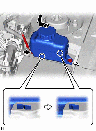
.png) | Connector |
.png) | Bolt |
 | Remove in this Direction |
(b) Move the brake master cylinder reservoir assembly as shown in the illustration to disengage the 2 claws, and disconnect it.
4. REMOVE RESERVOIR BRACKET
Click here
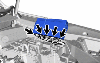
5. REMOVE NO. 1 RELAY BLOCK COVER
(a) Disengage the claw and 2 guides to remove the No. 1 relay block cover as indicated by the arrows, in the order shown in the illustration.
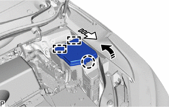
| | Remove in this Direction (1) |
 | Remove in this Direction (2) |
(b) Disengage the claw and 2 guides to remove the No. 1 relay block cover as indicated by the arrows, in the order shown in the illustration.
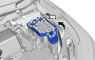
| | Remove in this Direction (1) |
| | Remove in this Direction (2) |
6. REMOVE SEMICONDUCTOR POWER INTEGRATION ECU
(a) Disengage the 2 claws.
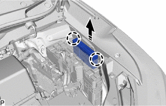
| | Remove in this Direction |
(b) Pull up the semiconductor power integration ECU as shown in the illustration.
NOTICE:
When pulling the semiconductor power integration ECU, take care not to damage it.
| (c) Disconnect the 5 connectors and remove the semiconductor power integration ECU. NOTICE: When pulling the semiconductor power integration ECU, take care not to damage it. |
|
 On-vehicle Inspection
ON-VEHICLE INSPECTION PROCEDURE 1. INSPECT SEMICONDUCTOR POWER INTEGRATION ECU (SIGNAL READING CHECK) NOTICE: Both present and history signal readings will be cleared if the semiconductor power integr ...
 Inspection
INSPECTION PROCEDURE 1. INSPECT SEMICONDUCTOR POWER INTEGRATION ECU (a) IG2 RELAY: (1) Measure the resistance according to the value(s) in the table below. Standard Resistance: Tester Connecti ...
Other materials:
Lexus RX (RX 350L, RX450h) 2016-2026 Repair Manual > Audio And Visual System (for 12.3 Inch Display): Portable Player cannot be Registered
CAUTION / NOTICE / HINT HINT: Some versions of "Bluetooth" compatible audio players may not function properly, or the functions may be limited using the radio receiver assembly, even if the portable audio player itself can play files. Click here PROCEDURE 1. CHECK THAT PORTABLE PLAYER IS "Bl ...
Lexus RX (RX 350L, RX450h) 2016-2026 Repair Manual > Power Back Door Control Switch: Inspection
INSPECTION PROCEDURE 1. INSPECT POWER BACK DOOR SWITCH (INTEGRATION CONTROL AND PANEL ASSEMBLY) (a) Check the operation of the power back door switch (integration control and panel assembly). (1) Measure the resistance according to the value(s) in the table below. Standard Resistance: Tester ...
Lexus RX (RX 350L, RX450h) 2016-{YEAR} Owners Manual
- For your information
- Pictorial index
- For safety and security
- Instrument cluster
- Operation of each component
- Driving
- Lexus Display Audio system
- Interior features
- Maintenance and care
- When trouble arises
- Vehicle specifications
- For owners
Lexus RX (RX 350L, RX450h) 2016-{YEAR} Repair Manual

0.1162