Lexus RX (RX 350L, RX450h) 2016-2026 Repair Manual: IG Power Source Circuit
DESCRIPTION
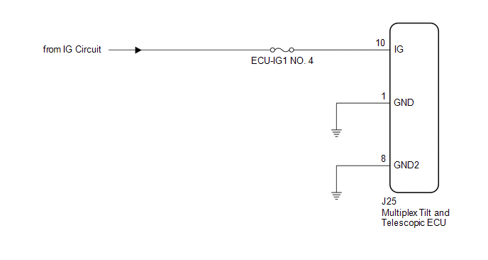
When the engine switch is turned on (IG), the IG power source circuit supplies positive (+) voltage to the multiplex tilt and telescopic ECU.
The multiplex tilt and telescopic ECU also receives engine switch signals via this circuit.
WIRING DIAGRAM
CAUTION / NOTICE / HINT
HINT:
Inspect the fuses for circuits related to this system before performing the following procedure.
PROCEDURE
| 1. | CHECK HARNESS AND CONNECTOR (MULTIPLEX TILT AND TELESCOPIC ECU - BATTERY) |
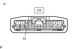
| (a) Disconnect the J25 multiplex tilt and telescopic ECU connector. |
|
(b) Measure the voltage according to the value(s) in the table below.
Standard Voltage:
| Tester Connection | Condition | Specified Condition |
|---|---|---|
| J25-10 (IG) - Body ground | Engine switch on (IG) | 11 to 14 V |
| NG | .gif) | REPAIR OR REPLACE HARNESS OR CONNECTOR |
|
.gif)
| 2. | CHECK HARNESS AND CONNECTOR (MULTIPLEX TILT AND TELESCOPIC ECU - BODY GROUND) |
| (a) Disconnect the J25 multiplex tilt and telescopic ECU connector. |
|
.png)
(b) Measure the resistance according to the value(s) in the table below.
Standard Resistance:
| Tester Connection | Condition | Specified Condition |
|---|---|---|
| J25-1 (GND) - Body ground | Always | Below 1 Ω |
| J25-8 (GND2) - Body ground | Always | Below 1 Ω |
| OK | | PROCEED TO NEXT SUSPECTED AREA SHOWN IN PROBLEM SYMPTOMS TABLE |
| NG | | REPAIR OR REPLACE HARNESS OR CONNECTOR |
 How To Proceed With Troubleshooting
CAUTION / NOTICE / HINT HINT: *: Use the Techstream. PROCEDURE 1. VEHICLE BROUGHT TO WORKSHOP
NEXT 2. INSPECT BATTERY VOLTAGE Standard voltage: 11 to 14 V If the vo ...
 Parts Location
PARTS LOCATION ILLUSTRATION *1 TILT AND TELESCOPIC SWITCH *2 ELECTRIC POWER STEERING COLUMN SUB-ASSEMBLY (TILT STEERING GEAR ASSEMBLY W/ MOTOR) - TELESCOPIC MOTOR - TILT MOTOR *3 COMBI ...
Other materials:
Lexus RX (RX 350L, RX450h) 2016-2026 Repair Manual > Axle And Differential: Front Axle Hub Bolt
ComponentsCOMPONENTS ILLUSTRATION *1 FRONT AXLE HUB BOLT *2 FRONT DISC *3 FRONT DISC BRAKE CALIPER ASSEMBLY - - Tightening torque for "Major areas involving basic vehicle performance such as moving/turning/stopping" : N*m (kgf*cm, ft.*lbf) ● Non-reusable part Repl ...
Lexus RX (RX 350L, RX450h) 2016-2026 Repair Manual > Transmission Control Cable: Components
COMPONENTS ILLUSTRATION *1 AIR CLEANER CAP WITH AIR CLEANER HOSE *2 AIR CLEANER CASE SUB-ASSEMBLY *3 AIR CLEANER FILTER ELEMENT SUB-ASSEMBLY *4 INLET AIR CLEANER ASSEMBLY *5 BATTERY *6 COOL AIR INTAKE DUCT SEAL *7 BATTERY TRAY *8 BATTERY CLAMP SUB-ASSEMBLY ...
Lexus RX (RX 350L, RX450h) 2016-{YEAR} Owners Manual
- For your information
- Pictorial index
- For safety and security
- Instrument cluster
- Operation of each component
- Driving
- Lexus Display Audio system
- Interior features
- Maintenance and care
- When trouble arises
- Vehicle specifications
- For owners
Lexus RX (RX 350L, RX450h) 2016-{YEAR} Repair Manual

0.013