
Lexus RX (RX 350L, RX450h) 2016-2025 Repair Manual: GVIF Disconnected (from Park Assist/Monitoring ECU to EMV/MM Integrated Device) (B1574)
DESCRIPTION
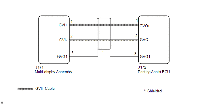
The multi-display assembly and parking assist ECU are connected via video signal (digital) lines.
This DTC is stored when a video signal (digital) line is disconnected.
| DTC No. | Detection Item | DTC Detection Condition | Trouble Area |
|---|---|---|---|
| B1574 | GVIF Disconnected (from Park Assist/Monitoring ECU to EMV/MM Integrated Device) | GVIF disconnected (from parking assist ECU to multi-display assembly) |
|
WIRING DIAGRAM
CAUTION / NOTICE / HINT
NOTICE:
Depending on the parts that are replaced or operations that are performed during vehicle inspection or maintenance, calibration of other systems as well as the panoramic view monitor system may be needed.
Click here .gif)
PROCEDURE
| 1. | CHECK DTC |
(a) Clear the DTCs.
Body Electrical > Navigation System > Clear DTCs(b) Turn the engine switch off.
(c) Turn the engine switch on (IG).
(d) Change the shift position to R and check for DTCs.
Body Electrical > Navigation System > Trouble CodesOK:
No DTCs are output.
| OK |  | USE SIMULATION METHOD TO CHECK |
|

| 2. | CHECK HARNESS AND CONNECTOR (MULTI-DISPLAY ASSEMBLY - PARKING ASSIST ECU) |
| (a) Disconnect the J171 multi-display assembly connector. |
|
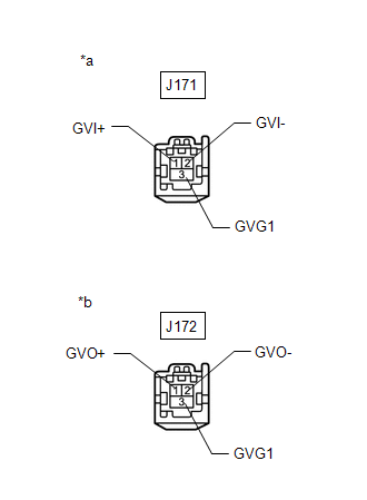
(b) Disconnect the J172 parking assist ECU connector.
(c) Measure the resistance according to the value(s) in the table below.
Standard Resistance:
| Tester Connection | Condition | Specified Condition |
|---|---|---|
| J172-2 (GVO-) - J171-2 (GVI-) | Always | Below 1 Ω |
| J172-1 (GVO+) - J171-1 (GVI+) | Always | Below 1 Ω |
| J172-3 (GVG1) - J171-3 (GVG1) | Always | Below 1 Ω |
| J172-2 (GVO-) or J171-2 (GVI-) - Body ground | Always | 10 kΩ or higher |
| J172-1 (GVO+) or J171-1 (GVI+) - Body ground | Always | 10 kΩ or higher |
| J172-3 (GVG1) or J171-3 (GVG1) - Body ground | Always | 10 kΩ or higher |
| NG | | REPAIR OR REPLACE HARNESS OR CONNECTOR |
|
| 3. | CHECK MULTI-DISPLAY ASSEMBLY |
(a) Replace the multi-display assembly with a new or known good one.
Click here
(b) Clear the DTCs.
Body Electrical > Navigation System > Clear DTCs(c) Turn the engine switch off.
(d) Recheck for DTCs and check that no DTCs are output.
Body Electrical > Navigation System > Trouble CodesOK:
No DTCs are output.
| OK | | END (MULTI-DISPLAY ASSEMBLY IS DEFECTIVE) |
| NG | | REPLACE PARKING ASSIST ECU |
 Touch Pad Vibration Driver Malfunction (B155A)
DESCRIPTION This DTC is stored if the remote touch (remote operation controller assembly) detects a malfunction in itself, such as internal hardware failure or remote touch screen vibration driver mal ...
 GVIF Disconnected (from EMV/MM Integrated Device to Multi Display) (B1575)
DESCRIPTION The radio receiver assembly and multi-display assembly are connected via video signal (digital) lines. This DTC is stored when a video signal (digital) line is disconnected. DTC No. D ...
Other materials:
Lexus RX (RX 350L, RX450h) 2016-2025 Repair Manual > Meter / Gauge System: Customize Parameters
CUSTOMIZE PARAMETERS CUSTOMIZE METER / GAUGE SYSTEM (a) Customizing with the Techstream (1) Connect the Techstream to the DLC3. (2) Turn the engine switch on (IG). (3) Turn the Techstream on. (4) Enter the following menus: Customize Setting / Warning or Display. (5) Select the setting by referring t ...
Lexus RX (RX 350L, RX450h) 2016-2025 Repair Manual > Center Power Outlet Socket(for Rear No. 1 Seat): Components
COMPONENTS ILLUSTRATION *1 ARMREST ASSEMBLY *2 CENTER ARMREST HINGE COVER LH *3 NO. 1 SEAT ARMREST ASSEMBLY *4 REAR SEATBACK BOARD SUB-ASSEMBLY *5 REAR SEATBACK COVER *6 REAR SEATBACK CENTER HINGE SUB-ASSEMBLY *7 NO. 2 REAR SEAT RECLINING SPACER - - Tig ...
Lexus RX (RX 350L, RX450h) 2016-{YEAR} Owners Manual
- For your information
- Pictorial index
- For safety and security
- Instrument cluster
- Operation of each component
- Driving
- Lexus Display Audio system
- Interior features
- Maintenance and care
- When trouble arises
- Vehicle specifications
- For owners
Lexus RX (RX 350L, RX450h) 2016-{YEAR} Repair Manual

0.0199