Lexus RX (RX 350L, RX450h) 2016-2026 Repair Manual: Components
COMPONENTS
ILLUSTRATION
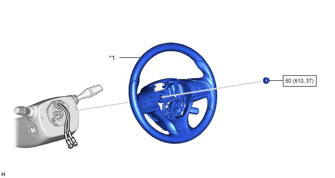
| *1 | STEERING WHEEL ASSEMBLY | - | - |
.png) | N*m (kgf*cm, ft.*lbf): Specified torque | - | - |
ILLUSTRATION
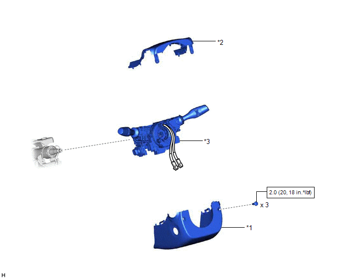
| *1 | LOWER STEERING COLUMN COVER | *2 | UPPER STEERING COLUMN COVER |
| *3 | TURN SIGNAL SWITCH ASSEMBLY WITH SPIRAL CABLE SUB-ASSEMBLY | - | - |
| | N*m (kgf*cm, ft.*lbf): Specified torque | - | - |
ILLUSTRATION
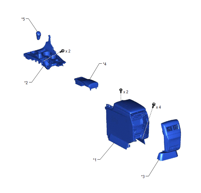
| *1 | CONSOLE BOX ASSEMBLY | *2 | CONSOLE PANEL SUB-ASSEMBLY |
| *3 | CONSOLE REAR END PANEL SUB-ASSEMBLY | *4 | REAR CONSOLE UPPER PANEL |
| *5 | SHIFT LEVER KNOB SUB-ASSEMBLY | - | - |
ILLUSTRATION
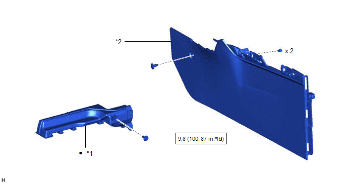
| *1 | NO. 4 AIR DUCT SUB-ASSEMBLY | *2 | FRONT NO. 1 CONSOLE BOX INSERT |
| | N*m (kgf*cm, ft.*lbf): Specified torque | ● | Non-reusable part |
ILLUSTRATION
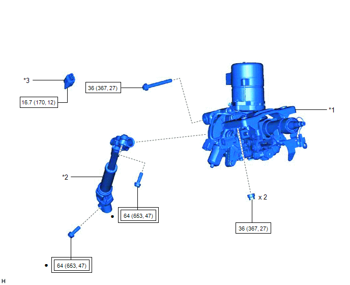
| *1 | STEERING COLUMN ASSEMBLY | *2 | STEERING INTERMEDIATE SHAFT ASSEMBLY |
| *3 | STOP LIGHT SWITCH ASSEMBLY | - | - |
 | Tightening torque for "Major areas involving basic vehicle performance such as moving/turning/stopping" : N*m (kgf*cm, ft.*lbf) | | N*m (kgf*cm, ft.*lbf): Specified torque |
| ● | Non-reusable part | - | - |
ILLUSTRATION
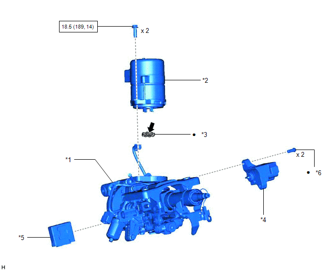
| *1 | ELECTRIC POWER STEERING COLUMN SUB-ASSEMBLY | *2 | POWER STEERING ECU ASSEMBLY |
| *3 | ELECTRIC POWER STEERING MOTOR SHAFT DAMPER | *4 | STEERING LOCK ACTUATOR OR UPPER BRACKET ASSEMBLY |
| *5 | MULTIPLEX TILT AND TELESCOPIC ECU | *6 | STEERING LOCK SET BOLT |
| | N*m (kgf*cm, ft.*lbf): Specified torque | ● | Non-reusable part |
.png) | Grease | - | - |

 Disassembly
DISASSEMBLY CAUTION / NOTICE / HINT NOTICE:
Do not drop the power steering ECU assembly, strike it with tools or subject it to impacts.
If the power steering ECU assembly is subjected to an impac ...
Other materials:
Lexus RX (RX 350L, RX450h) 2016-2026 Repair Manual > Camshaft Oil Control Solenoid (for Bank 1): Components
COMPONENTS ILLUSTRATION *1 CAMSHAFT TIMING OIL CONTROL SOLENOID ASSEMBLY (for Intake Side of Bank 1) *2 CAMSHAFT TIMING OIL CONTROL SOLENOID ASSEMBLY (for Exhaust Side of Bank 1) *3 O-RING - - N*m (kgf*cm, ft.*lbf): Specified torque ● Non-reusable part Adhesiv ...
Lexus RX (RX 350L, RX450h) 2016-2026 Repair Manual > Rear Crossing Traffic Alert Buzzer (w/o Rear No. 2 Seat): Components
COMPONENTS ILLUSTRATION *A for TMC Made *B for TMMC Made *1 DECK BOARD ASSEMBLY *2 DECK SIDE TRIM BOX RH *3 FRONT DECK FLOOR BOX *4 REAR DECK FLOOR BOX *5 REAR FLOOR FINISH PLATE *6 REAR NO. 3 FLOOR BOARD *7 REAR NO. 4 FLOOR BOARD *8 TONNEAU COVER AS ...
Lexus RX (RX 350L, RX450h) 2016-{YEAR} Owners Manual
- For your information
- Pictorial index
- For safety and security
- Instrument cluster
- Operation of each component
- Driving
- Lexus Display Audio system
- Interior features
- Maintenance and care
- When trouble arises
- Vehicle specifications
- For owners
Lexus RX (RX 350L, RX450h) 2016-{YEAR} Repair Manual

0.0109