
Lexus RX (RX 350L, RX450h) 2016-2026 Repair Manual: Terminals Of Ecu
TERMINALS OF ECU
TERMINAL INSPECTION

| *a | Component without harness connected (Steering Lock ECU (Steering Lock Actuator or Upper Bracket Assembly)) | - | - |
(a) Measure the voltage and resistance according to the value(s) in the table below.
| Terminal No. (Symbol) | Input/Output | Wiring Color | Terminal Description | Condition | Specified Condition | Related Data List Item |
|---|---|---|---|---|---|---|
| L1-1 (GND) - Body ground | - | W-B - Body ground | Ground* | Always | Below 1 Ω | - |
| L1-3 (IGE) - L1-1 (GND) | Input | SB - W-B | Steering lock motor activation command signal (motor activation command signal sent from certification ECU (smart key ECU assembly)) | Any door opened when conditions below met, and then steering lock motor activated:
| Pulse generation (see waveform) | Smart Access
|
| L1-4 (SLP1) - L1-1 (GND) | Output | GR - W-B | Steering lock bar position signal (output signal from steering unlock sensor) | Steering locked → unlocked | 11 to 14 V → Below 1.5 V | Smart Access
|
| L1-5 (LIN) - L1-1 (GND) | Input/Output | R - W-B | LIN communication line | - | - | Smart Access
|
| L1-6 (IG2) - L1-1 (GND) | Input | P - W-B | Power source mode signal (IG2 power supply input for entire steering lock actuator or upper bracket assembly)* | Engine switch off → engine switch on (IG) | Below 1 V → 11 to 14 V | - |
| L1-7 (B) - Body ground | Input | V - Body ground | Power source* | Always | 11 to 14 V | - |
- *: When there is a problem with the power source input, the certification ECU (smart key ECU assembly) may store DTC B2786.
NOTICE:
There is 1 motor and 2 sensors built into the steering lock actuator or upper bracket assembly.
HINT:
- When taking measurements when the lock motor is stopped, it is not necessary to perform any operations.
-
In order to take measurements when the lock motor is operating, perform either of the following operations:
- To unlock the steering, carry the key and turn the engine switch on (ACC) or on (IG).
- To lock the steering, turn the engine switch off with the shift lever in P, and then open a door.
(1) Waveform
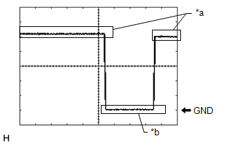
| *a | Steering Lock Motor not Operating |
| *b | Steering Lock Motor Operating |
| Item | Content |
|---|---|
| Tester Connection | L1-3 (IGE) - L1-1 (GND) |
| Tool Setting | 2 V/DIV., 200 ms./DIV. |
| Vehicle Condition | Steering lock motor not operating → Operating → Not operating |
 System Diagram
SYSTEM DIAGRAM Circuit Description Component Outline Steering Lock ECU (Steering Lock Actuator or Upper Bracket Assembly)
The steering is locked and unlocked by communicating with the c ...
 Unable to Unlock Steering Wheel (Engine cannot Start)
DESCRIPTION The steering lock actuator or upper bracket assembly activates the steering lock motor and moves the lock bar into the steering column to lock the steering. The steering may not unlock whe ...
Other materials:
Lexus RX (RX 350L, RX450h) 2016-2026 Repair Manual > Dynamic Radar Cruise Control System: Problem Symptoms Table
PROBLEM SYMPTOMS TABLE NOTICE:
Before replacing the ECM, refer to Registration.
Click here
When replacing the millimeter wave radar sensor assembly, always replace it with a new one. If a millimeter wave radar sensor assembly which was installed to another vehicle is used, the information st ...
Lexus RX (RX 350L, RX450h) 2016-2026 Repair Manual > Towing Converter System: Parts Location
PARTS LOCATION ILLUSTRATION *1 TOWING CONVERTER RELAY *2 TOWING SOCKET *3 ENGINE ROOM RELAY BLOCK - SEMICONDUCTOR POWER INTEGRATION ECU - TOWING FUSE *4 INSTRUMENT PANEL JUNCTION BLOCK ASSEMBLY - TAIL FUSE *5 COMBINATION METER ASSEMBLY - - ...
Lexus RX (RX 350L, RX450h) 2016-{YEAR} Owners Manual
- For your information
- Pictorial index
- For safety and security
- Instrument cluster
- Operation of each component
- Driving
- Lexus Display Audio system
- Interior features
- Maintenance and care
- When trouble arises
- Vehicle specifications
- For owners
Lexus RX (RX 350L, RX450h) 2016-{YEAR} Repair Manual

0.0115