Lexus RX (RX 350L, RX450h) 2016-2026 Repair Manual: Removal
REMOVAL
CAUTION / NOTICE / HINT
The necessary procedures (adjustment, calibration, initialization, or registration) that must be performed after parts are removed, installed, or replaced during the power steering ECU assembly removal/installation are shown below.
Necessary Procedure After Parts Removed/Installed/Replaced| Replacement Part or Procedure | Necessary Procedures | Effects / Inoperative when not performed | Link |
|---|---|---|---|
|
*1: When performing learning using the Techstream.
Click here | |||
| Replacement of the power steering ECU assembly |
|
| |
| Replacement of the electric power steering column sub-assembly | Perform Torque Sensor Zero Point Calibration | ||
| Replacement of the steering lock actuator or upper bracket assembly | Perform code registration (Immobiliser system) |
| |
| Removal/installation of the spiral cable with sensor sub-assembly |
| Parking assist monitor system | |
| Steering angle neutral point (Initialize panoramic view monitor system) | Panoramic view monitor system | | |
| Steering angle neutral point (Initialize intelligent clearance sonar system) |
| | |
| Disconnect cable from negative battery terminal | Memorize steering angle neutral point | Lane Control System | |
| Pre-collision system | |||
| Intelligent clearance sonar system*1 | |||
| Lighting system (w/ Automatic Headlight Beam Level Control System) | | ||
| Parking assist monitor system | | ||
| Panoramic view monitor system | | ||
| Initialize back door lock | Power door lock control system | | |
| Reset back door close position | Power Back Door System (w/ Outside Door Control Switch) | | |
PROCEDURE
1. REMOVE STEERING COLUMN ASSEMBLY
Click here .gif)
2. REMOVE STEERING LOCK ACTUATOR OR UPPER BRACKET ASSEMBLY
Click here
3. REMOVE POWER STEERING ECU ASSEMBLY
NOTICE:
- Do not drop the power steering ECU assembly, strike it with tools or subject it to impacts.
- If the power steering ECU assembly is subjected to an impact, replace it with a new one.
- Do not pull the wire harness of the power steering ECU assembly.
- Do not allow any moisture to come into contact with the power steering ECU assembly.
- Do not loosen any bolts not mentioned in the procedure.
- Do not allow any foreign matter to contaminate the power steering ECU assembly.
| (a) Disconnect the connector. |
|
.png)
| (b) Remove the 2 bolts and power steering ECU assembly from the electric power steering column sub-assembly. |
|
.png)
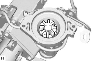
| (c) Remove the electric power steering motor shaft damper from the electric power steering column sub-assembly. |
|
 Installation
INSTALLATION PROCEDURE 1. INSTALL POWER STEERING ECU ASSEMBLY NOTICE:
Do not drop the power steering ECU assembly, strike it with tools or subject it to impacts.
If the power steering ECU assembl ...

Other materials:
Lexus RX (RX 350L, RX450h) 2016-2026 Repair Manual > Curtain Shield Airbag Assembly (w/o Rear No. 2 Seat): Removal
REMOVAL CAUTION / NOTICE / HINT The necessary procedures (adjustment, calibration, initialization, or registration) that must be performed after parts are removed, installed, or replaced during the curtain shield airbag assembly removal/installation are shown below. Necessary Procedure After Parts R ...
Lexus RX (RX 350L, RX450h) 2016-2026 Repair Manual > Front Radar Sensor System: Front Radar Sensor Optical Axis Misalignment Malfunction (C1A1100)
DESCRIPTION The millimeter wave radar sensor assembly performs self-diagnosis to check for misalignment of its beam axis. If misalignment is detected, the millimeter wave radar sensor assembly stores DTC C1A1100. DTC No. Detection Item DTC Detection Condition Trouble Area C1A1100 Fron ...
Lexus RX (RX 350L, RX450h) 2016-{YEAR} Owners Manual
- For your information
- Pictorial index
- For safety and security
- Instrument cluster
- Operation of each component
- Driving
- Lexus Display Audio system
- Interior features
- Maintenance and care
- When trouble arises
- Vehicle specifications
- For owners
Lexus RX (RX 350L, RX450h) 2016-{YEAR} Repair Manual

0.0113