Lexus RX (RX 350L, RX450h) 2016-2026 Repair Manual: Installation
INSTALLATION
PROCEDURE
1. INSTALL POWER STEERING ECU ASSEMBLY
NOTICE:
- Do not drop the power steering ECU assembly, strike it with tools or subject it to impacts.
- If the power steering ECU assembly is subjected to an impact, replace it with a new one.
- Do not pull the wire harness of the power steering ECU assembly.
- Do not allow any moisture to come into contact with the power steering ECU assembly.
- Do not loosen any bolts not mentioned in the procedure.
- Do not allow any foreign matter to contaminate the power steering ECU assembly.
| (a) Install 2 service nuts to the steering main shaft. Recommended Service Nut: Thread Diameter 12.0 mm (0.472 in.) Thread Pitch 1.25 mm (0.0492 in.) |
|
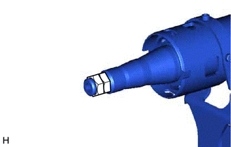
(b) Simultaneously rotate the service nut that was installed first counterclockwise and rotate the service nut that was installed second clockwise to lock them.
NOTICE:
Do not apply excessive torque to the service nuts by using a tool such as an impact wrench.
HINT:
The service nuts are used for turning the steering main shaft during inspection of the steering main shaft rotating torque.
Remove the service nuts after performing this procedure.
.png) | Grease |
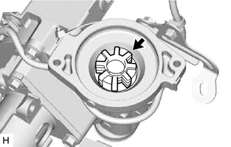
(c) Apply grease to a new electric power steering motor shaft damper.
NOTICE:
First wipe off the existing grease from the serrated part, and then apply the dedicated grease supplied with a new power steering ECU assembly or electric power steering column sub-assembly.
(d) Install the electric power steering motor shaft damper to the electric power steering column sub-assembly.
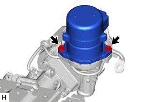
| (e) Temporarily install the power steering ECU assembly to the electric power steering column sub-assembly with the 2 bolts. NOTICE: When temporarily installing the 2 bolts to the power steering ECU assembly, do not tighten them all the way down. |
|
| (f) Secure the steering column assembly in a vise using aluminum plates, cloths and wooden blocks. NOTICE:
|
|
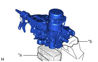
| (g) Rotate the steering main shaft 180 degrees counterclockwise and then 180 degrees clockwise at a speed of 60 rpm, and repeat 2 to 3 times to center the axis of the power steering ECU assembly. [*1] |
|
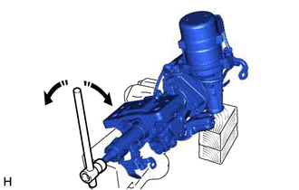
(h) Tighten the 2 bolts. [*2]
Torque:
18.5 N·m {189 kgf·cm, 14 ft·lbf}
| (i) Using a torque wrench, measure the turning torque of the steering main shaft. Preload: 1.3 to 2.7 N*m (13.3 to 27.5 kgf*cm, 11.6 to 23.8 in.*lbf) NOTICE: Ensure that there is no abnormal resistance during rotation. If the turning torque is not as specified, loosen the 2 bolts and repeat steps [*1] and [*2] to recenter the axis of the power steering ECU assembly. |
|
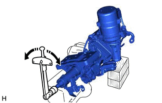
(j) Remove the 2 service nuts.
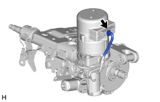
| (k) Connect the connector. |
|
2. INSTALL STEERING LOCK ACTUATOR OR UPPER BRACKET ASSEMBLY
Click here 
3. INSTALL STEERING COLUMN ASSEMBLY
Click here
4. TORQUE SENSOR ZERO POINT CALIBRATION
Click here
5. ASSIST MAP WRITING
Click here
 Components
COMPONENTS ILLUSTRATION *1 ELECTRIC POWER STEERING COLUMN SUB-ASSEMBLY *2 POWER STEERING ECU ASSEMBLY *3 ELECTRIC POWER STEERING MOTOR SHAFT DAMPER *4 STEERING LOCK ACTUATOR OR UPP ...
 Removal
REMOVAL CAUTION / NOTICE / HINT The necessary procedures (adjustment, calibration, initialization, or registration) that must be performed after parts are removed, installed, or replaced during the po ...
Other materials:
Lexus RX (RX 350L, RX450h) 2016-2026 Repair Manual > Steering Pad Switch: Inspection
INSPECTION PROCEDURE 1. INSPECT STEERING PAD SWITCH ASSEMBLY (a) Measure the resistance according to the value(s) in the table below. Text in Illustration *A w/ Lane Departure Alert System - - *a Component without harness connected (Steering Pad Switch Assembly) *b Seek+ *c ...
Lexus RX (RX 350L, RX450h) 2016-2026 Repair Manual > Transmission Control Cable: Adjustment
ADJUSTMENT CAUTION / NOTICE / HINT NOTICE: Before installing the transmission control cable assembly, check that the park/neutral position switch assembly and the shift lever are in neutral. PROCEDURE 1. SECURE VEHICLE (a) Fully apply the parking brake and chock a wheel. CAUTION:
Make sure to app ...
Lexus RX (RX 350L, RX450h) 2016-{YEAR} Owners Manual
- For your information
- Pictorial index
- For safety and security
- Instrument cluster
- Operation of each component
- Driving
- Lexus Display Audio system
- Interior features
- Maintenance and care
- When trouble arises
- Vehicle specifications
- For owners
Lexus RX (RX 350L, RX450h) 2016-{YEAR} Repair Manual

0.0119