Lexus RX (RX 350L, RX450h) 2016-2026 Repair Manual: Terminals Of Ecu
TERMINALS OF ECU
STEERING WHEEL HEATER CONTROL ASSEMBLY
HINT:
Perform the inspection from the harness side with the connectors connected.
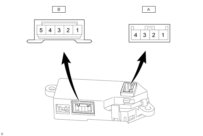
(a) Measure the voltage or resistance according to the value(s) in the table below.
| Terminal No. (Symbol) | Terminal Description | Condition | Specified Condition |
|---|---|---|---|
| A-4 (IG) - Body ground | IG power supply | Engine switch on (IG) | 11 to 14 V |
| A-3 (SW) - Body ground | Steering heater switch (Integration control&panel assembly) input signal | Engine switch on (IG), Steering heater switch (Integration control&panel assembly) pressed and held | 11 to 14 V |
| A-2 (LED) - Body ground | LED output signal | Engine switch on (IG), Heated steering wheel system operating | Below 3 V |
| A-1 (GND) - Body ground | Ground | Always | Below 1 Ω |
| B-5 (SH1) - Body ground | Heater output signal | Engine switch on (IG), Heated steering wheel system operating | 11 to 14 V*1 |
| B-3 (TH1) - Body ground | Thermistor input signal | Engine switch on (IG), Heated steering wheel system operating on at 0 to 40°C (32 to 104°F) | 2.5 to 4.8 V*2 |
| B-2 (TH2) - Body ground | Thermistor ground | Engine switch on (IG), Heated steering wheel system operating | Below 1 V |
| B-1 (SH2) - Body ground | Heater ground | Engine switch on (IG), Heated steering wheel system operating | Below 1 V |
HINT:
- *1: The current to the heater turns ON/OFF depending on the temperature of the thermistor. As a result, it may take several minutes before a voltage value is output.
- *2: When ambient temperature is 0 to 40°C (32 to 104°F).
 System Diagram
SYSTEM DIAGRAM SYSTEM DIAGRAM ...
 Multiplex Tilt And Telescopic Ecu
ComponentsCOMPONENTS ILLUSTRATION *1 LOWER STEERING COLUMN COVER *2 MULTIPLEX TILT AND TELESCOPIC ECU N*m (kgf*cm, ft.*lbf): Specified torque - - InstallationINSTALLATION PROCE ...
Other materials:
Lexus RX (RX 350L, RX450h) 2016-2026 Repair Manual > Rear Power Seat Control System(for Second Row): Precaution
PRECAUTION POWER FOLDING SEAT FUNCTION HANDLING PRECAUTIONS NOTICE:
When a rear power seat is operating, make sure that the area around the seat is free of obstructions.
When a rear power seat is operating, be careful not to allow any part of your body or foreign objects to interfere with the s ...
Lexus RX (RX 350L, RX450h) 2016-2026 Repair Manual > Rear No. 1 Seat Inner Belt Assembly(for 60/40 Split Seat Type Rh Side): Installation
INSTALLATION PROCEDURE 1. INSTALL REAR SEAT 3 POINT TYPE BELT ASSEMBLY RH (a) Install the rear seat 3 point type belt assembly RH with the bolt. Torque: 42 N·m {428 kgf·cm, 31 ft·lbf} (b) Engage the 2 clamps. (c) Connect the connector. 2. INSTALL REAR NO. 1 SEAT RECLINING ADJUSTER INSIDE COVER C ...
Lexus RX (RX 350L, RX450h) 2016-{YEAR} Owners Manual
- For your information
- Pictorial index
- For safety and security
- Instrument cluster
- Operation of each component
- Driving
- Lexus Display Audio system
- Interior features
- Maintenance and care
- When trouble arises
- Vehicle specifications
- For owners
Lexus RX (RX 350L, RX450h) 2016-{YEAR} Repair Manual

0.0112