Lexus RX (RX 350L, RX450h) 2016-2026 Repair Manual: Removal
REMOVAL
CAUTION / NOTICE / HINT
The necessary procedures (adjustment, calibration, initialization, or registration) that must be performed after parts are removed, installed, or replaced during the electric power steering column sub-assembly removal/installation are shown below.
Necessary Procedure After Parts Removed/Installed/Replaced| Replacement Part or Procedure | Necessary Procedures | Effects / Inoperative when not performed | Link |
|---|---|---|---|
|
*1: When performing learning using the Techstream.
Click here | |||
| Replacement of the power steering ECU assembly |
|
| |
| Replacement of the electric power steering column sub-assembly | Perform Torque Sensor Zero Point Calibration | ||
| Replacement of the steering lock actuator or upper bracket assembly | Perform code registration (Immobiliser system) |
| |
| Removal/installation of the spiral cable with sensor sub-assembly |
| Parking assist monitor system | |
| Steering angle neutral point (Initialize panoramic view monitor system) | Panoramic view monitor system | | |
| Steering angle neutral point (Initialize intelligent clearance sonar system) |
| | |
| Disconnect cable from negative battery terminal | Memorize steering angle neutral point | Lane Control System | |
| Pre-collision system | |||
| Intelligent clearance sonar system*1 | |||
| Lighting system (w/ Automatic Headlight Beam Level Control System) | | ||
| Parking assist monitor system | | ||
| Panoramic view monitor system | | ||
| Initialize back door lock | Power door lock control system | | |
| Reset back door close position | Power Back Door System (w/ Outside Door Control Switch) | | |
PROCEDURE
1. PRECAUTION
Click here .gif)
2. CHANGE POWER TILT AND POWER TELESCOPIC STEERING COLUMN SYSTEM SETTINGS
(a) Disable the auto tilt away function by changing the customize settings.
Click here
NOTICE:
Record the current customize setting (whether the auto tilt away function is enabled or disabled) in order to restore the current setting after finishing the operation.
HINT:
Performing the above operation causes the auto tilt away function to be disabled when the engine switch is turned off.
(b) Turn the engine switch on (IG). Operate the tilt and telescopic switch to fully extend and lower the steering column assembly.
3. ALIGN FRONT WHEELS FACING STRAIGHT AHEAD
4. REMOVE HORN BUTTON ASSEMBLY
Click here
5. REMOVE STEERING WHEEL ASSEMBLY
Click here
6. REMOVE LOWER STEERING COLUMN COVER
| (a) Remove the 3 screws. |
|
.png)
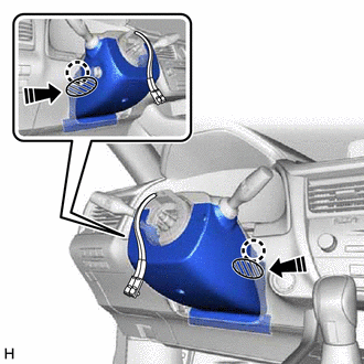
 | Push Area |
.png) | Push in this direction |
(b) While pressing the push area shown in the illustration to disengage the 2 claws, slightly lower the lower steering column cover.
7. REMOVE UPPER STEERING COLUMN COVER
(a) Disengage the 2 claws and separate the upper steering column cover.
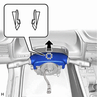
| | Separate in this direction |
| (b) Disengage the 6 clips to remove the upper steering column cover. |
|
.png)
8. REMOVE TURN SIGNAL SWITCH ASSEMBLY WITH SPIRAL CABLE SUB-ASSEMBLY
NOTICE:
- Do not replace the spiral cable with sensor sub-assembly with the battery connected and the engine switch on (IG).
- Do not rotate the spiral cable with sensor sub-assembly without the steering wheel assembly installed, with the battery connected and the engine switch on (IG).
- Ensure that the steering wheel assembly is installed and aligned straight when inspecting the steering sensor.
(a) Disconnect each connector from the turn signal switch assembly with spiral cable sub-assembly.
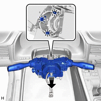
| | Remove in this direction |
(b) Disengage the 3 claws to remove the turn signal switch assembly with spiral cable sub-assembly from the steering column assembly.
9. REMOVE LOWER NO. 1 INSTRUMENT PANEL AIRBAG ASSEMBLY
Click here
10. REMOVE REAR CONSOLE UPPER PANEL
Click here
11. REMOVE SHIFT LEVER KNOB SUB-ASSEMBLY
Click here
12. REMOVE CONSOLE PANEL SUB-ASSEMBLY
Click here
13. REMOVE CONSOLE REAR END PANEL SUB-ASSEMBLY
Click here
14. REMOVE CONSOLE BOX ASSEMBLY
Click here
15. REMOVE FRONT NO. 1 CONSOLE BOX INSERT
Click here
16. REMOVE NO. 4 AIR DUCT SUB-ASSEMBLY
| (a) Remove the bolt. |
|
.png)
| (b) Disengage the 3 claws to remove the No. 4 air duct sub-assembly. |
|
.png)
17. REMOVE STOP LIGHT SWITCH ASSEMBLY
Click here
18. SEPARATE STEERING INTERMEDIATE SHAFT ASSEMBLY
Click here
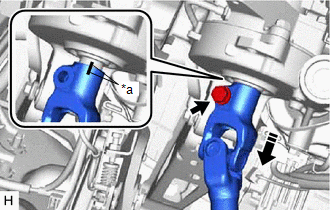
19. REMOVE STEERING INTERMEDIATE SHAFT ASSEMBLY
| (a) Loosen the bolt. |
|
.png)
| (b) Remove the bolt and slide the steering intermediate shaft assembly. NOTICE: Do not remove the steering intermediate shaft assembly from the steering column assembly. |
|
(c) Put matchmarks on the steering intermediate shaft assembly and the steering column assembly.
(d) Remove the steering intermediate shaft assembly from the steering column assembly.
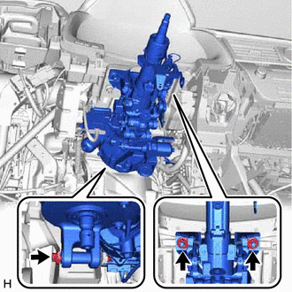
20. REMOVE STEERING COLUMN ASSEMBLY
| (a) Disconnect the 2 connectors. |
|
.png)
(b) Disengage the clamp.
(c) Disconnect each connector and disengage each wire harness clamp from the steering column assembly.
| (d) Remove the bolt, 2 nuts and steering column assembly. |
|
 Reassembly
REASSEMBLY CAUTION / NOTICE / HINT NOTICE:
Do not drop the power steering ECU assembly, strike it with tools or subject it to impacts.
If the power steering ECU assembly is subjected to an impact ...

Other materials:
Lexus RX (RX 350L, RX450h) 2016-2026 Repair Manual > Side Turn Signal Light Assembly: Removal
REMOVAL CAUTION / NOTICE / HINT The necessary procedures (adjustment, calibration, initialization, or registration) that must be performed after parts are removed and installed, or replaced during side turn signal light assembly removal/installation are shown below. Necessary Procedure After Parts R ...
Lexus RX (RX 350L, RX450h) 2016-2026 Repair Manual > Audio And Visual System (for 8 Inch Display): AV Signal Stoppage (Low Battery Voltage) (B158F)
DESCRIPTION This DTC is stored when a video or audio signal is interrupted due to battery voltage input to the radio receiver assembly dropping temporarily. DTC No. Detection Item DTC Detection Condition Trouble Area B158F AV Signal Stoppage (Low Battery Voltage) A video or audio si ...
Lexus RX (RX 350L, RX450h) 2016-{YEAR} Owners Manual
- For your information
- Pictorial index
- For safety and security
- Instrument cluster
- Operation of each component
- Driving
- Lexus Display Audio system
- Interior features
- Maintenance and care
- When trouble arises
- Vehicle specifications
- For owners
Lexus RX (RX 350L, RX450h) 2016-{YEAR} Repair Manual

0.0161