
Lexus RX (RX 350L, RX450h) 2016-2026 Repair Manual: Removal
REMOVAL
CAUTION / NOTICE / HINT
The necessary procedures (adjustment, calibration, initialization, or registration) that must be performed after parts are removed, installed, or replaced during the steering wheel assembly removal/installation are shown below.
Necessary Procedure After Parts Removed/Installed/Replaced| Replacement Part or Procedure | Necessary Procedures | Effects / Inoperative when not performed | Link |
|---|---|---|---|
|
*1: When performing learning using the Techstream.
Click here | |||
| Disconnect cable from negative battery terminal | Memorize steering angle neutral point | Lane Control System | |
| Pre-collision system | |||
| Intelligent clearance sonar system*1 | |||
| Lighting system (w/ Automatic Headlight Beam Level Control System) | | ||
| Parking assist monitor system | | ||
| Panoramic view monitor system | | ||
| Initialize back door lock | Power door lock control system | | |
| Reset back door close position | Power Back Door System (w/ Outside Door Control Switch) | | |
PROCEDURE
1. ALIGN FRONT WHEELS FACING STRAIGHT AHEAD
2. REMOVE HORN BUTTON ASSEMBLY
Click here .gif)
3. REMOVE STEERING WHEEL ASSEMBLY
(a) Disconnect each connector from the spiral cable with sensor sub-assembly.
| (b) Remove the steering wheel assembly set nut. |
|
.png)
(c) Put matchmarks on the steering wheel assembly and steering main shaft.
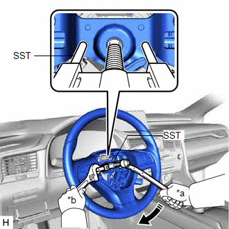
| (d) Using SST, remove the steering wheel assembly. SST: 09950-50013 09951-05010 09952-05010 09953-05020 09954-05070 NOTICE: Apply a small amount of grease to the threads and tip of SST (09953-05020) before use. |
|
4. REMOVE CRUISE CONTROL MAIN SWITCH
Click here
5. REMOVE STEERING PAD SWITCH ASSEMBLY
Click here
6. REMOVE SHIFT PADDLE SWITCH (TRANSMISSION SHIFT SWITCH ASSEMBLY)
for U881F: Click here
for U881E: Click here
7. REMOVE NO. 1 SWITCH WIRE
for U881F: Click here
for U881E: Click here
8. REMOVE STEERING VIBRATION AND HEATER ECU
Click here
 Installation
INSTALLATION CAUTION / NOTICE / HINT NOTICE:
Do not replace the spiral cable with sensor sub-assembly with the battery connected and the engine switch on (IG).
Do not rotate the spiral cable with ...
 Tilt And Telescopic Manual Switch
InspectionINSPECTION PROCEDURE 1. INSPECT TILT AND TELESCOPIC SWITCH (a) Remove the tilt and telescopic switch. Click here *a Component without harness connected (Tilt and Telescop ...
Other materials:
Lexus RX (RX 350L, RX450h) 2016-2026 Repair Manual > Air Conditioning System: Air Outlet Damper Control Servo Motor Circuit(Driver Side Front A/C Rear Air Flow) (B1486/86)
DESCRIPTION The Rear No. 1 cooling unit damper servo sub-assembly sends pulse signals to inform the air conditioning amplifier assembly of the damper position. The air conditioning amplifier assembly activates the motor (normal or reverse) based on these signals to move the Rear No. 1 cooling unit d ...
Lexus RX (RX 350L, RX450h) 2016-2026 Repair Manual > Blind Spot Monitor System: Blind Spot Monitor Master Module Beam Axis Inspection Incomplete (C1ABB)
DESCRIPTION This DTC is stored when a beam axis adjustment has not been performed for the blind spot monitor sensor LH. HINT: This DTC is always stored after replacing a blind spot monitor sensor. The purpose of this DTC is to ensure that a beam axis adjustment is performed. Completing the beam axis ...
Lexus RX (RX 350L, RX450h) 2016-{YEAR} Owners Manual
- For your information
- Pictorial index
- For safety and security
- Instrument cluster
- Operation of each component
- Driving
- Lexus Display Audio system
- Interior features
- Maintenance and care
- When trouble arises
- Vehicle specifications
- For owners
Lexus RX (RX 350L, RX450h) 2016-{YEAR} Repair Manual

0.0124