Lexus RX (RX 350L, RX450h) 2016-2026 Repair Manual: Removal
REMOVAL
CAUTION / NOTICE / HINT
The necessary procedures (adjustment, calibration, initialization, or registration) that must be performed after parts are removed and installed, or replaced during steering gear assembly removal/installation are shown below.
Necessary Procedures After Parts Removed/Installed/Replaced| Replaced Part or Performed Procedure | Necessary Procedure | Effect/Inoperative Function when Necessary Procedure not Performed | Link |
|---|---|---|---|
| Front wheel alignment adjustment | Calibration |
| |
PROCEDURE
1. ALIGN FRONT WHEELS FACING STRAIGHT AHEAD
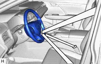
2. SECURE STEERING WHEEL
| (a) Secure the steering wheel with the seat belt in order to prevent rotation. HINT: This operation is useful to prevent damage to the spiral cable. |
|
3. REMOVE FRONT WHEELS
Click here .gif)
4. REMOVE NO. 2 ENGINE UNDER COVER
Click here
5. SEPARATE STEERING INTERMEDIATE SHAFT ASSEMBLY
| (a) Put matchmarks on the steering link assembly and steering intermediate shaft assembly. |
|
.png)
(b) Remove the bolt.
(c) Separate the steering intermediate shaft assembly from the steering link assembly.
6. SEPARATE FRONT STABILIZER LINK ASSEMBLY LH
| (a) Remove the nut and separate the front stabilizer link assembly LH from the front stabilizer bar. HINT: If the ball joint turns together with the nut, use a 6 mm hexagon socket wrench to hold the stud bolt. |
|
.png)
7. SEPARATE FRONT STABILIZER LINK ASSEMBLY RH
HINT:
Perform the same procedure as for the LH side.
8. SEPARATE TIE ROD ASSEMBLY LH
| (a) Remove the cotter pin and nut. |
|
.png)
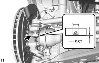
| (b) Install SST to the tie rod assembly LH. SST: 09960-20010 09961-02060 NOTICE: Make sure that the upper ends of the tie rod assembly LH and SST are aligned. |
|
(c) Secure SST using a string.
NOTICE:
Be sure to tighten the string firmly to secure SST to the steering knuckle LH to prevent SST from falling off.
(d) Using SST, separate the tie rod assembly LH from the steering knuckle LH.
SST: 09960-20010
09961-02010
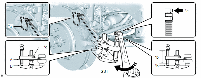
| *a | String | *b | Molybdenum Grease Application Area |
| *c | Place wrench here | *d | Center Nut |
.png) | Turn | - | - |
CAUTION:
Apply molybdenum grease to the bolt threads and the tip of SST.
NOTICE:
- Be sure to tighten the string firmly to secure SST to the steering knuckle LH to prevent SST from falling off.
- Install SST with the center nut so that (A) and (B) shown in the illustration are parallel. Otherwise, the ball joint dust cover may be damaged.
- Be sure to place the wrench on the part shown in the illustration.
- Do not damage the front disc brake dust cover.
- Do not damage the ball joint dust cover.
- Do not damage the steering knuckle LH.
9. SEPARATE TIE ROD ASSEMBLY RH
HINT:
Perform the same procedure as for the LH side.
10. SEPARATE FRONT NO. 1 STABILIZER BRACKET LH
| (a) Remove the 2 bolts and separate the front No. 1 stabilizer bracket LH from the front frame assembly. |
|
.png)
11. SEPARATE FRONT NO. 1 STABILIZER BRACKET RH
HINT:
Perform the same procedure as for the LH side.
12. REMOVE FRONT NO. 2 STABILIZER BRACKET LH
(a) Remove the front No. 2 stabilizer bracket LH from the front frame assembly.
13. REMOVE FRONT NO. 2 STABILIZER BRACKET RH
HINT:
Perform the same procedure as for the LH side.
14. SEPARATE FRONT STABILIZER BAR
(a) Separate the front stabilizer bar from the front frame assembly.
NOTICE:
Use wire or an equivalent tool to secure the front stabilizer bar.
15. REMOVE STEERING LINK ASSEMBLY
| (a) Remove the 2 bolts, 2 nuts and steering link assembly from the front frame assembly. NOTICE: Because the nut has its own stopper, do not turn the nut. Loosen the bolt with the nut secured. |
|
.png)
16. SECURE STEERING LINK ASSEMBLY
| (a) Using SST, secure the steering link assembly in a vise. SST: 09612-00012 HINT: Wrap SST with protective tape before use. |
|
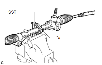
17. REMOVE TIE ROD ASSEMBLY LH
| (a) Put matchmarks on the tie rod assembly LH and steering gear assembly. |
|
.png)
(b) Remove the tie rod assembly LH and lock nut.
18. REMOVE TIE ROD ASSEMBLY RH
HINT:
Perform the same procedure as for the LH side.