Lexus RX (RX 350L, RX450h) 2016-2026 Repair Manual: Disassembly
DISASSEMBLY
CAUTION / NOTICE / HINT
The necessary procedures (adjustment, calibration, initialization or registration) that must be performed after parts are removed and installed, or replaced during front door disassembly/reassembly are shown below.
Necessary Procedures After Parts Removed/Installed/Replaced| Replaced Part or Performed Procedure | Necessary Procedure | Effect/Inoperative Function when Necessary Procedure not Performed | Link |
|---|---|---|---|
|
*1: When performing learning using the Techstream.
Click here | |||
| Disconnect cable from negative (-) battery terminal | Memorize steering angle neutral point | Lane Control System | |
| Pre-collision System | |||
| Intelligent Clearance Sonar System*1 | |||
| Parking Assist Monitor System | | ||
| Panoramic View Monitor System | | ||
| Lighting System (w/ Automatic Headlight Beam Level Control System) | | ||
| Initialize back door lock | Power Door Lock Control System | | |
| Reset back door close position | Power Back Door System (w/ Outside Door Control Switch) | | |
| Side television camera view adjustment | Panoramic view monitor system | |
| Initialize Power Window Control System |
| |
HINT:
- Use the same procedure for the RH side and LH side.
- The following procedure is for the LH side.
PROCEDURE
1. PRECAUTION
CAUTION:
Be sure to read Precaution thoroughly before servicing.
Click here .gif)
NOTICE:
After turning the engine switch off, waiting time may be required before disconnecting the cable from the negative (-) battery terminal. Therefore, make sure to read the disconnecting the cable from the negative (-) battery terminal notices before proceeding with work.
Click here
2. DISCONNECT CABLE FROM NEGATIVE BATTERY TERMINAL
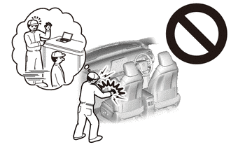
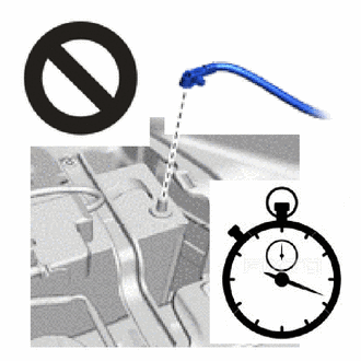
CAUTION:
Wait at least 90 seconds after disconnecting the cable from the negative (-) battery terminal to disable the SRS system.
NOTICE:
When disconnecting the cable, some systems need to be initialized after the cable is reconnected.
Click here
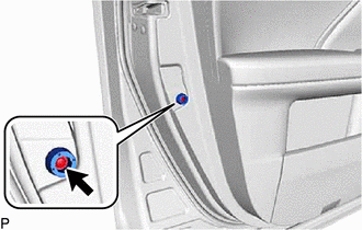
3. REMOVE FRONT DOOR INSIDE HANDLE BEZEL PLUG
| (a) Using a moulding remover, disengage the 3 claws to remove the front door inside handle bezel plug. |
|
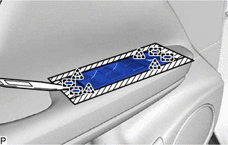
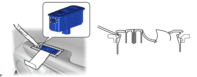
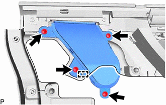
4. REMOVE MULTIPLEX NETWORK MASTER SWITCH ASSEMBLY WITH FRONT DOOR UPPER ARMREST BASE PANEL (for Driver Side)
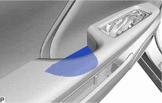
(a) Apply protective tape to the front door armrest assembly as shown in the illustration.
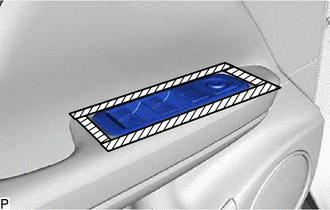
 | Protective Tape |
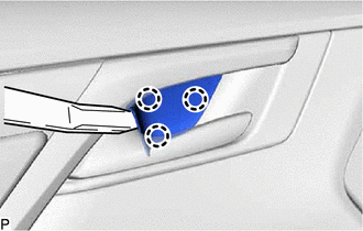
| (b) Using a moulding remover E or equivalent, disengage the 4 clips and 4 guides. |
|
(c) Disconnect the connector to remove the multiplex network master switch assembly with front door upper armrest base panel.
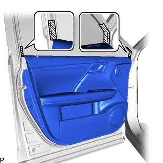
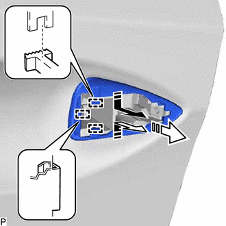
5. REMOVE POWER WINDOW REGULATOR SWITCH ASSEMBLY WITH FRONT DOOR UPPER ARMREST BASE PANEL (for Front Passenger Side)
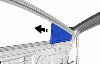
(a) Apply protective tape to the front door armrest assembly as shown in the illustration.
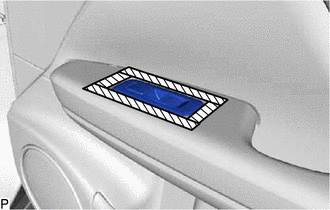
| | Protective Tape |
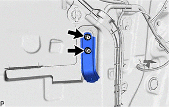
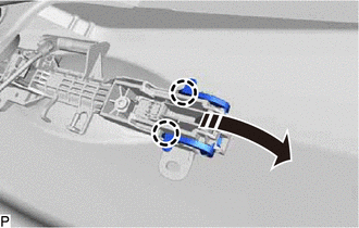
(b) Raise the power window regulator switch assembly with front door upper armrest base panel using the moulding remover D as shown in the illustration.
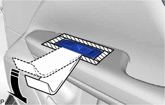
.png) | Move in this Direction |
(c) While holding the moulding remover D, disengage the claw using the moulding remover E or equivalent as shown in the illustration.
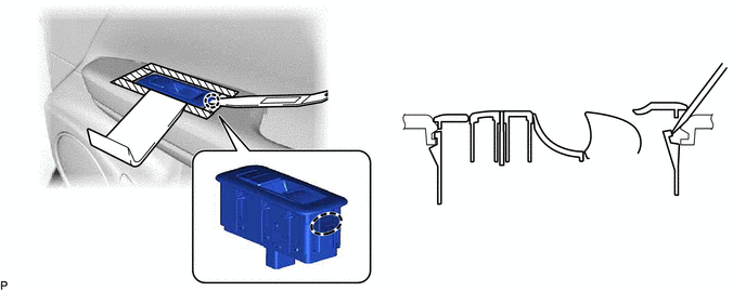
.png) | Insert Moulding Remover E or Equivalent Here | - | - |
(d) While holding the moulding remover D, disengage the claw using the moulding remover E or equivalent as shown in the illustration.
| | Insert Moulding Remover E or Equivalent Here | - | - |
(e) Disconnect the connector to remove the power window regulator switch assembly with front door upper armrest base panel.
6. REMOVE DOOR ARMREST COVER
| (a) Remove the door armrest cover. |
|
7. REMOVE COURTESY LIGHT ASSEMBLY
Click here
8. REMOVE FRONT DOOR NO. 1 STIFFENER CUSHION
| (a) Remove the screw and front door No. 1 stiffener cushion. |
|
9. REMOVE FRONT DOOR TRIM BOARD SUB-ASSEMBLY
(a) Apply protective tape to the front door panel as shown in the illustration.
| | Protective Tape |
| (b) Remove the 3 screws. |
|
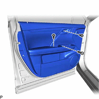
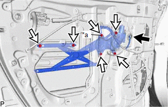
(c) Using a clip remover, disengage the 10 clips and remove the front door trim board sub-assembly as shown in the illustration.
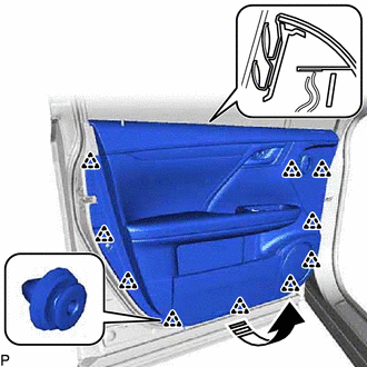
| | Remove in this Direction |
(d) Disconnect each connector.
(e) Disconnect the front door lock remote control cable assembly from the front door inside handle sub-assembly as shown in the illustration.
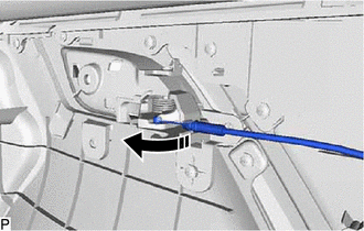
| | Remove in this Direction |
(f) Disengage the 2 claws as shown in the illustration to disconnect the front door inside locking cable assembly and remove the front door trim board sub-assembly.
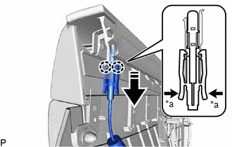
| | Remove in this Direction |
| *a | Push |
10. REMOVE SEAT MEMORY SWITCH (w/ Memory)
Click here
11. REMOVE FRONT DOOR INNER GLASS WEATHERSTRIP
| (a) Disengage the 6 claws and remove the front door inner glass weatherstrip as shown in the illustration. |
|
12. REMOVE FRONT DOOR AIR DUCT
| (a) Remove the 4 screws. |
|
(b) Disengage the guide to remove the front door air duct.
13. REMOVE DOOR LOCK CONTROL KNOB BEZEL
(a) Disengage the 2 claws and remove the door lock control knob bezel as shown in the illustration.
| | Remove in this Direction |
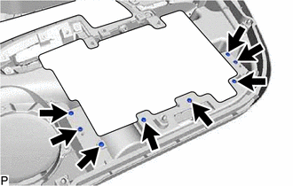
14. REMOVE FRONT DOOR TRIM POCKET
| (a) Remove the 8 screws and front door trim pocket. |
|
15. REMOVE OUTER MIRROR CONTROL ECU ASSEMBLY
Click here
16. REMOVE OUTER MIRROR PROTECTOR
Click here
17. REMOVE OUTER MIRROR INSTALL HOLE COVER
Click here
18. REMOVE OUTER REAR VIEW MIRROR ASSEMBLY
Click here
19. REMOVE FRONT NO. 1 SPEAKER ASSEMBLY
Click here
20. REMOVE FRONT DOOR NO. 1 TRIM BRACKET
| (a) Remove the 2 screws and front door No. 1 trim bracket. |
|
21. REMOVE FRONT DOOR SERVICE HOLE COVER
| (a) Disconnect the connector. |
|
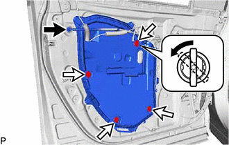
(b) Turn the front door weatherstrip clip 45 degrees and remove the 4 front door weatherstrip clips as shown in the illustration.
| (c) Disengage the 5 clamps. |
|
| (d) Disengage the 5 clips to remove the front door service hole cover. |
|
22. REMOVE DOOR SIDE AIRBAG SENSOR
Click here
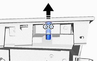
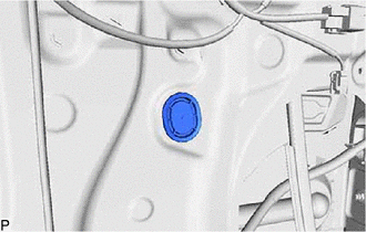
23. REMOVE FRONT DOOR GLASS SUB-ASSEMBLY
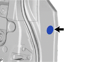
| (a) Remove the hole plug. |
|
(b) for Driver Side:
(1) Connect the multiplex network master switch assembly.
(c) for Front Passenger Side:
(1) Connect the power window regulator switch assembly.
(d) Connect the cable to the negative (-) battery terminal.
(e) Turn the engine switch on (IG).
(f) Move the front door glass sub-assembly so that the door glass bolts can be seen.
(g) Turn the engine switch off.
(h) Disconnect the cable from the negative (-) battery terminal.
(i) for Driver Side:
(1) Disconnect the multiplex network master switch assembly.
(j) for Front Passenger Side:
(1) Disconnect the power window regulator switch assembly.
| (k) Remove the 2 bolts. NOTICE: After the bolts are removed, do not allow the front door glass sub-assembly to fall. |
|
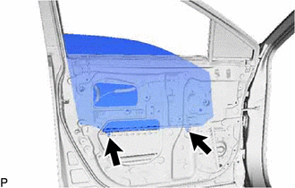
(l) Remove the front door glass sub-assembly as indicated by the arrows, in the order shown in the illustration.
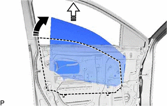
| | Remove in this Direction (1) |
 | Remove in this Direction (2) |
NOTICE:
Do not damage the front door glass sub-assembly.
24. REMOVE FRONT DOOR WINDOW REGULATOR ASSEMBLY
| (a) Disengage the 2 claws to remove the front door No. 2 service hole cover. |
|
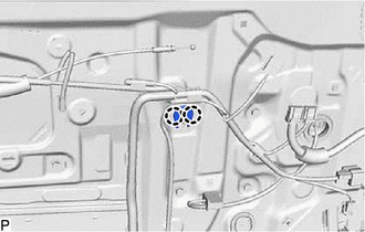
| (b) Disconnect the connector. |
|
(c) Loosen the temporary bolt.
NOTICE:
Do not remove the temporary bolt. If the temporary bolt is removed, the front door window regulator assembly may fall and cause damage.
(d) Remove the 5 bolts.
(e) Remove the front door window regulator assembly.
(f) Remove the temporary bolt from the front door window regulator assembly.
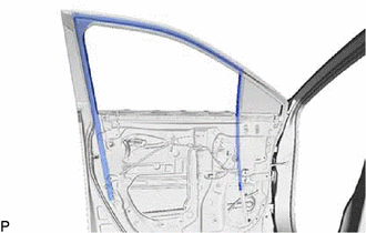
25. REMOVE FRONT DOOR GLASS RUN
| (a) Remove the front door glass run. |
|
26. REMOVE FRONT DOOR REAR LOWER FRAME SUB-ASSEMBLY
(a) Remove the 2 bolts.
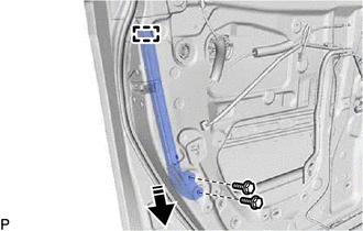
| | Remove in this Direction |
(b) Disengage the guide and remove the front door rear lower frame sub-assembly as shown in the illustration.
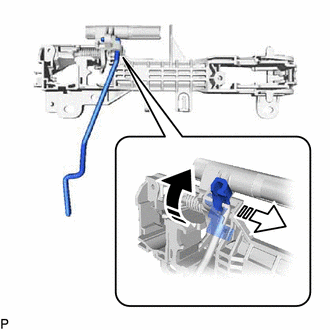
27. REMOVE FRONT DOOR OUTSIDE HANDLE ASSEMBLY
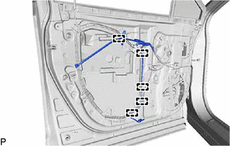
| (a) Disengage the clamp. |
|
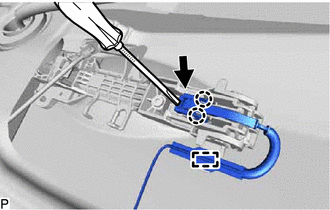
(b) Disengage the 2 claws.
(c) Using a screwdriver, disconnect the connector.
(d) Disengage the 2 claws and move the lever as shown in the illustration.
| | Disengage in this Direction |
(e) Remove the front door outside handle assembly as shown in the illustration.
| | Remove in this Direction |
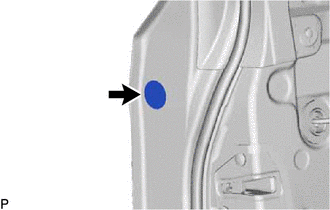
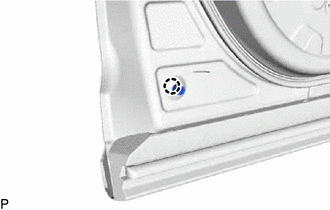
28. REMOVE FRONT DOOR LOCK CYLINDER ASSEMBLY (for Driver Side)
| (a) Remove the hole plug. |
|
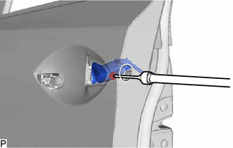
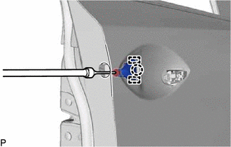
| (b) Using a T30 "TORX" socket wrench, loosen the screw and remove the front door lock cylinder assembly. HINT: The screw cannot be removed because it is integrated into the front door outside handle frame sub-assembly. |
|
29. REMOVE FRONT DOOR OUTSIDE HANDLE COVER (for Front Passenger Side)
| (a) Remove the hole plug. |
|
| (b) Using a T30 "TORX" socket wrench, loosen the screw. HINT: The screw cannot be removed because it is integrated into the front door outside handle frame sub-assembly. |
|
(c) Disengage the 2 guides and claw to remove the front door outside handle cover.
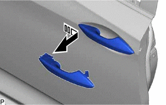
30. REMOVE FRONT DOOR FRONT OUTSIDE HANDLE PAD
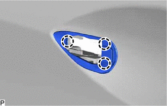
| (a) Disengage the 3 claws to remove the front door front outside handle pad. |
|
31. REMOVE FRONT DOOR REAR OUTSIDE HANDLE PAD
| (a) Disengage the claw. |
|
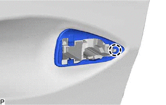
(b) Disengage the 3 guides to remove the front door rear outside handle pad as shown in the illustration.
| | Remove in this Direction (1) |
| | Remove in this Direction (2) |
32. REMOVE FRONT DOOR LOCK WITH MOTOR ASSEMBLY
Click here
33. REMOVE FRONT DOOR OUTSIDE HANDLE FRAME SUB-ASSEMBLY
| (a) Using a T30 "TORX" socket wrench, remove the screw. |
|
(b) Slide the front door outside handle frame sub-assembly to disengage the claw and remove the front door outside handle frame sub-assembly.
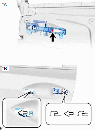
34. REMOVE FRONT DOOR LOCK OPEN ROD
(a) Remove the front door lock open rod as indicated by the arrows, in the order shown in the illustration.
| | Remove in this Direction (1) |
| | Remove in this Direction (2) |
35. REMOVE FRONT DOOR CHECK ASSEMBLY
(a) Remove the 2 nuts and bolt, and front door check assembly.
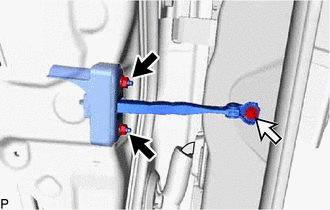
.png) | Nut |
.png) | Bolt |
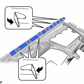
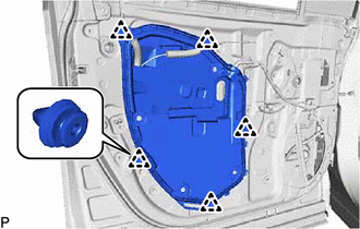
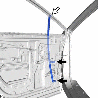
36. REMOVE FRONT DOOR WEATHERSTRIP
(a) Using a clip remover, disengage the 25 clips and remove the front door weatherstrip.
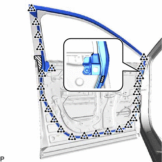
| | Double-sided Tape |
37. REMOVE FRONT DOOR PANEL PROTECTOR
| (a) Remove the front door panel protector. |
|
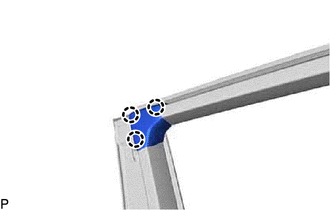
38. REMOVE FRONT DOOR VENT SEAL
| (a) Remove the front door vent seal. |
|
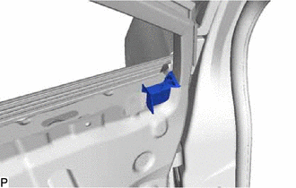
39. REMOVE UPPER DOOR FRAME GARNISH
| (a) Disengage the 3 claws to remove the upper door frame garnish. |
|
40. REMOVE FRONT DOOR FRONT LOWER FRAME SUB-ASSEMBLY
(a) Remove the 2 bolts, screw and front door front lower frame sub-assembly.
| | Bolt |
| | Screw |
41. REMOVE FRONT DOOR FIX WINDOW GLASS
(a) Remove the front door fix window glass with the front door fix window weatherstrip as shown in the illustration.
| | Remove in this Direction |
(b) Remove the front door fix window glass from the front door fix window weatherstrip.
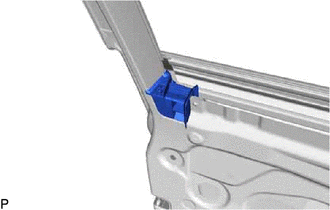
42. REMOVE FRONT DOOR PANEL CUSHION
| (a) Disengage the claw to remove the front door panel cushion. |
|
43. REMOVE FRONT DOOR BELT MOULDING ASSEMBLY
Click here
44. REMOVE FRONT DOOR REAR WINDOW FRAME MOULDING
Click here
45. REMOVE FRONT DOOR UPPER WINDOW FRAME MOULDING
Click here
46. REMOVE FRONT DOOR REAR OUTSIDE STRIPE
Click here
47. REMOVE FRONT DOOR STRIPE
Click here
48. REMOVE NO. 1 BLACK OUT TAPE
Click here
49. REMOVE FRONT DOOR OUTSIDE MOULDING SUB-ASSEMBLY
Click here
50. REMOVE FRONT DOOR SCUFF PLATE
w/o Rear No. 2 Seat:
Click here
w/ Rear No. 2 Seat:
Click here
51. REMOVE COWL SIDE TRIM BOARD
Click here
52. REMOVE FRONT DOOR FRONT WINDOW FRAME MOULDING
Click here
 Adjustment
ADJUSTMENT CAUTION / NOTICE / HINT *a Centering Bolt *b Standard Bolt HINT:
Use the same procedure for the RH side and LH side.
The following procedure is for the LH side.
Center ...
 Reassembly
REASSEMBLY CAUTION / NOTICE / HINT HINT:
Use the same procedure for the RH side and LH side.
The following procedure is for the LH side.
PROCEDURE 1. PRECAUTION NOTICE: After turning the engin ...
Other materials:
Lexus RX (RX 350L, RX450h) 2016-2026 Repair Manual > Air Conditioning Unit: Reassembly
REASSEMBLY PROCEDURE 1. INSTALL NO. 1 COOLER THERMISTOR Click here 2. INSTALL NO. 1 COOLER EVAPORATOR SUB-ASSEMBLY (a) Install a new No. 1 cooler evaporator sub-assembly with No. 1 cooler thermistor to the upper heater case. NOTICE: When the No. 1 cooler evaporator sub-assembly is removed, make ...
Lexus RX (RX 350L, RX450h) 2016-2026 Repair Manual > Meter / Gauge System: Terminals Of Ecu
TERMINALS OF ECU COMBINATION METER ASSEMBLY (a) Measure the voltage and resistance according to the value(s) in the table below. Terminal No. (Symbol) Wiring Color Terminal Description Condition Specified Condition J10-2 (MSM+) - Body ground Y - Body ground Steering pad switch si ...
Lexus RX (RX 350L, RX450h) 2016-{YEAR} Owners Manual
- For your information
- Pictorial index
- For safety and security
- Instrument cluster
- Operation of each component
- Driving
- Lexus Display Audio system
- Interior features
- Maintenance and care
- When trouble arises
- Vehicle specifications
- For owners
Lexus RX (RX 350L, RX450h) 2016-{YEAR} Repair Manual

0.0109