Lexus RX (RX 350L, RX450h) 2016-2026 Repair Manual: Reassembly
REASSEMBLY
PROCEDURE
1. INSTALL NO. 1 COOLER THERMISTOR
Click here .gif)
2. INSTALL NO. 1 COOLER EVAPORATOR SUB-ASSEMBLY
| (a) Install a new No. 1 cooler evaporator sub-assembly with No. 1 cooler thermistor to the upper heater case. NOTICE: When the No. 1 cooler evaporator sub-assembly is removed, make sure to install a new one. The No. 1 cooler evaporator sub-assembly cannot be reused. |
|
.png)
(b) Engage the 2 clamps.
(c) Engage the 10 claws to install the upper heater case with No. 1 cooler evaporator sub-assembly to the lower heater case.
.png)
(d) Install the 2 screws.
3. INSTALL COOLER EXPANSION VALVE
(a) Sufficiently apply compressor oil to 2 new O-rings and the fitting surfaces of the No. 1 cooler evaporator sub-assembly.
Compressor Oil:
ND-OIL 12 or equivalent
(b) Install the 2 O-rings to the No. 1 cooler evaporator sub-assembly.
NOTICE:
Keep the O-rings and O-ring fitting surfaces free of foreign matter.
| (c) Using a 4 mm hexagon socket wrench, install the cooler expansion valve with the 2 hexagon bolts. Torque: 3.5 N·m {36 kgf·cm, 31 in·lbf} |
|
.png)
4. INSTALL COOLING UNIT PARTS
| (a) Install the cooling unit parts. |
|
.png)
5. INSTALL HEATER RADIATOR UNIT SUB-ASSEMBLY
.png) | Install in this Direction |
(a) Install the heater radiator unit sub-assembly as shown in the illustration.
| (b) Engage the 4 claws to install the heater clamp. |
|
.png)
6. INSTALL HEATER GROMMET
| (a) Install the heater grommet. |
|
.png)
7. INSTALL NO. 2 AIR CONDITIONING RADIATOR DAMPER SERVO SUB-ASSEMBLY
| (a) Using the reference points, install the No. 2 air conditioning radiator damper servo sub-assembly with the 2 screws. |
|
8. INSTALL NO. 3 AIR CONDITIONING RADIATOR DAMPER SERVO SUB-ASSEMBLY
| (a) Connect the 3 links of the No. 3 air conditioning radiator damper servo sub-assembly to the 3 links of the air conditioning radiator assembly as shown in the illustration. |
|
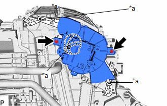
(b) Install the No. 3 air conditioning radiator damper servo sub-assembly with the 2 screws.
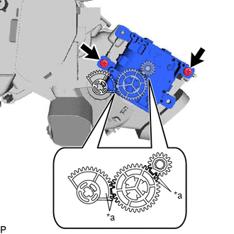
9. INSTALL NO. 1 AIR CONDITIONING RADIATOR DAMPER SERVO SUB-ASSEMBLY
(a) Align each gear on the air conditioner radiator assembly as shown in the illustration, and then check that the gears of the No. 1 air conditioning radiator damper servo sub-assembly are aligned as shown in the illustration.
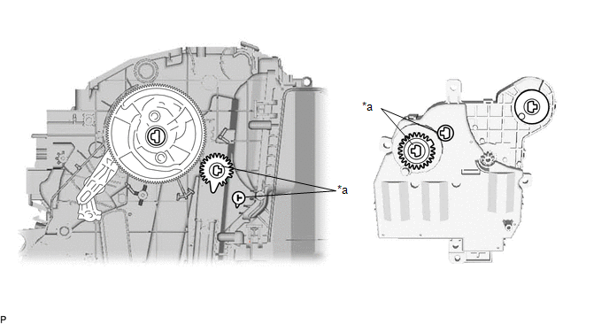
| *a | Reference Point | - | - |
(b) Using the reference points, install the No. 1 air conditioning radiator damper servo sub-assembly with the 3 screws.
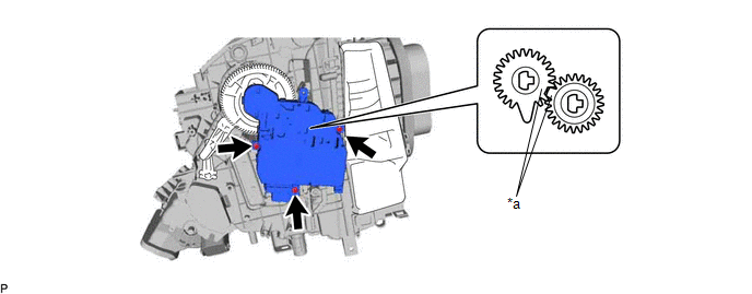
| *a | Reference Point | - | - |
10. INSTALL AIR CONDITIONING AMPLIFIER ASSEMBLY
Click here
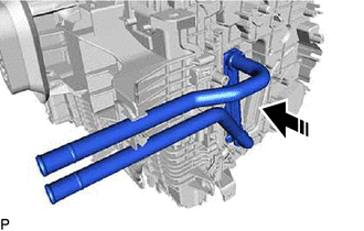
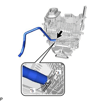
11. INSTALL DRAIN COOLER HOSE
| (a) Align the hose notch with the rib as shown in the illustration and install the drain cooler hose. |
|
12. INSTALL AIR CONDITIONING HARNESS ASSEMBLY
(a) Engage each clamp.
.png)
(b) Connect each connector to install the air conditioning harness assembly.
13. INSTALL HEATER COVER (w/o PTC Heater)
| | Install in this Direction |
(a) Engage the guide to install the heater cover as shown in the illustration.
14. INSTALL QUICK HEATER ASSEMBLY (w/ PTC Heater)
| | Install in this Direction |
(a) Engage the guide to install the quick heater assembly as shown in the illustration.
15. INSTALL NO. 2 HEATER COVER
| (a) Engage the guide and claw. |
|
.png)
(b) Install the No. 2 heater cover with the screw.
16. INSTALL BLOWER ASSEMBLY
Click here
17. INSTALL ID CODE BOX (IMMOBILISER CODE ECU)
Click here
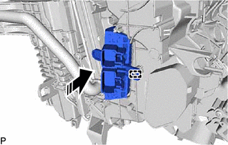
18. INSTALL ASPIRATOR
| (a) Engage the 2 claws to install the aspirator. |
|
.png)
19. INSTALL NO. 5 AIR DUCT SUB-ASSEMBLY
| (a) Engage the 3 claws. |
|
.png)
(b) Install a new No. 5 air duct sub-assembly with the screw.
 Installation
INSTALLATION PROCEDURE 1. TEMPORARILY INSTALL AIR CONDITIONER UNIT ASSEMBLY (a) Temporarily install the air conditioner unit assembly to the instrument panel reinforcement assembly with the 3 bolts. 2 ...
 Ambient Temperature Sensor
ComponentsCOMPONENTS ILLUSTRATION *1 COOL AIR INTAKE DUCT SEAL *2 COOLER (AMBIENT TEMP. SENSOR) THERMISTOR InspectionINSPECTION PROCEDURE 1. INSPECT COOLER (AMBIENT TEMP. SENSOR) THERMIST ...
Other materials:
Lexus RX (RX 350L, RX450h) 2016-2026 Repair Manual > Steering System: Adjustment
ADJUSTMENT PROCEDURE 1. STEERING WHEEL OFF CENTER ADJUSTMENT PROCEDURE (a) Inspect steering wheel off center. (1) Turn the steering wheel assembly to the center position. (2) Apply masking tape to the top center of the steering wheel assembly and upper steering column cover. *1 Ste ...
Lexus RX (RX 350L, RX450h) 2016-2026 Repair Manual > Parking Assist Monitor System: Reverse Signal Circuit
DESCRIPTION The multi-display assembly receives a reverse signal from the park/neutral position switch assembly*1 or clearance warning ECU assembly*2. *1: except 12.3 Inch Display and w/ Intuitive Parking Assist System *2: for 12.3 Inch Display and w/ Intuitive Parking Assist System WIRING DIAGRAM ...
Lexus RX (RX 350L, RX450h) 2016-{YEAR} Owners Manual
- For your information
- Pictorial index
- For safety and security
- Instrument cluster
- Operation of each component
- Driving
- Lexus Display Audio system
- Interior features
- Maintenance and care
- When trouble arises
- Vehicle specifications
- For owners
Lexus RX (RX 350L, RX450h) 2016-{YEAR} Repair Manual

0.013