Lexus RX (RX 350L, RX450h) 2016-2026 Repair Manual: Installation
INSTALLATION
PROCEDURE
1. INSTALL HOOD LOCK CONTROL CABLE ASSEMBLY
(a) Tie the string that was passed through the grommet to the end of the hood lock control cable assembly.
HINT:
- When changing the hood lock control cable assembly from type A to type B, the hood lock control lever sub-assembly must also be changed to type B.
- When changing the hood lock control cable assembly from type B to type A, the hood lock control lever sub-assembly must also be changed to type A.
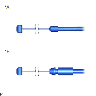
| *A | Type A |
| *B | Type B |
(b) Pass the hood lock control cable assembly through the grommet.
(c) Disconnect the string from the hood lock control cable assembly.
(d) Pass the hood lock control cable assembly through the upper radiator support.
(e) Engage the 3 clamps.
(f) Engage the clamp to install the hood lock control cable assembly.
2. INSTALL HOOD LOCK CONTROL LEVER SUB-ASSEMBLY
(a) Connect the hood lock control cable assembly to install the hood lock control lever sub-assembly.
HINT:
- When changing the hood lock control lever sub-assembly from type A to type B, the hood lock control cable assembly must also be changed to type B.
- When changing the hood lock control lever sub-assembly from type B to type A, the hood lock control cable assembly must also be changed to type A.
3. CONNECT HOOD LOCK CONTROL LEVER SUB-ASSEMBLY
Click here .gif)
4. INSTALL NO. 1 INSTRUMENT PANEL UNDER COVER SUB-ASSEMBLY
Click here
5. INSTALL HOOD LOCK ASSEMBLY
(a) Apply MP grease to the sliding areas of the hood lock assembly.
(b) Connect the hood lock control cable assembly.
| (c) Install the hood lock assembly with the 3 bolts. Torque: 8.0 N·m {82 kgf·cm, 71 in·lbf} |
|
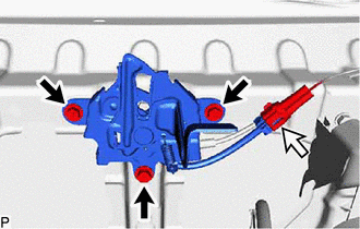
(d) Connect the connector.
6. INSTALL HOOD LOCK RELEASE LEVER PROTECTOR
(a) Engage the clamp.
(b) Install the hood lock release lever protector with the 2 clips.
7. INSTALL HOOD LOCK CONTROL CABLE COVER
(a) Engage the clamp.
(b) Install the hood lock control cable cover with the screw.
8. INSTALL OUTER COWL TOP PANEL SUB-ASSEMBLY
Click here
9. INSTALL FRONT WIPER MOTOR AND LINK ASSEMBLY
Click here
 Components
COMPONENTS ILLUSTRATION *1 OUTER COWL TOP PANEL SUB-ASSEMBLY - - N*m (kgf*cm, ft.*lbf): Specified torque - - ILLUSTRATION *1 HOOD LOCK ASSEMBLY *2 HOOD LOCK CONTROL C ...
 Removal
REMOVAL PROCEDURE 1. REMOVE FRONT WIPER MOTOR AND LINK ASSEMBLY Click here 2. REMOVE OUTER COWL TOP PANEL SUB-ASSEMBLY Click here 3. REMOVE HOOD LOCK CONTROL CABLE COVER (a) Remove the screw. ...
Other materials:
Lexus RX (RX 350L, RX450h) 2016-2026 Repair Manual > Steering Lock System: Unable to Unlock Steering Wheel (Engine cannot Start)
DESCRIPTION The steering lock actuator or upper bracket assembly activates the steering lock motor and moves the lock bar into the steering column to lock the steering. The steering may not unlock when the lock bar gets stuck in the lock hole of the steering column. In this case, if the engine switc ...
Lexus RX (RX 350L, RX450h) 2016-2026 Repair Manual > Sfi System: Actuator Supply Voltage "A" Stuck On (P06579E)
MONITOR DESCRIPTION The ECM monitors the output voltage to the throttle actuator. This self-check ensures that the ECM is functioning properly. The output voltage is usually 0 V when the engine switch is turned off. If the output voltage is 7 V or higher when the engine switch is turned off, the ECM ...
Lexus RX (RX 350L, RX450h) 2016-{YEAR} Owners Manual
- For your information
- Pictorial index
- For safety and security
- Instrument cluster
- Operation of each component
- Driving
- Lexus Display Audio system
- Interior features
- Maintenance and care
- When trouble arises
- Vehicle specifications
- For owners
Lexus RX (RX 350L, RX450h) 2016-{YEAR} Repair Manual

0.0114