Lexus RX (RX 350L, RX450h) 2016-2026 Repair Manual: Removal
REMOVAL
PROCEDURE
1. REMOVE FRONT WIPER MOTOR AND LINK ASSEMBLY
Click here .gif)
2. REMOVE OUTER COWL TOP PANEL SUB-ASSEMBLY
Click here
3. REMOVE HOOD LOCK CONTROL CABLE COVER
(a) Remove the screw.
| (b) Disengage the clamp and remove the hood lock control cable cover. |
|
4. REMOVE HOOD LOCK RELEASE LEVER PROTECTOR
(a) Remove the 2 clips.
| (b) Disengage the clamp to remove the hood lock release lever protector. |
|
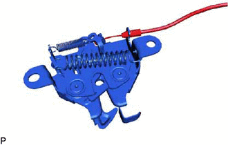
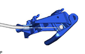
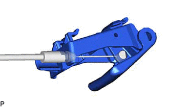
5. REMOVE HOOD LOCK ASSEMBLY
| (a) Disconnect the connector. |
|
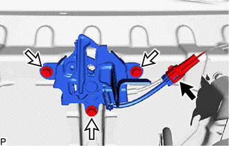
(b) Remove the 3 bolts.
| (c) Disconnect the hood lock control cable assembly to remove the hood lock assembly. |
|
6. REMOVE NO. 1 INSTRUMENT PANEL UNDER COVER SUB-ASSEMBLY
Click here
7. DISCONNECT HOOD LOCK CONTROL LEVER SUB-ASSEMBLY
Click here
8. REMOVE HOOD LOCK CONTROL LEVER SUB-ASSEMBLY
(a) for Type A:
| (1) Disconnect the hood lock control cable assembly to remove the hood lock control lever sub-assembly. HINT: When changing the hood lock control lever sub-assembly from type A to type B, the hood lock control cable assembly must also be changed to type B. |
|
(b) for Type B:
| (1) Disconnect the hood lock control cable assembly to remove the hood lock control lever sub-assembly. HINT: When changing the hood lock control lever sub-assembly from type B to type A, the hood lock control cable assembly must also be changed to type A. |
|
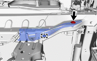
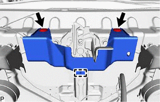
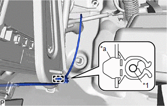
9. REMOVE HOOD LOCK CONTROL CABLE ASSEMBLY
| (a) Using a screwdriver, disengage the clamp as shown in the illustration. |
|
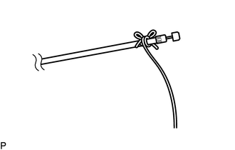
| (b) Tie a string to the hood lock control lever sub-assembly side end of the hood lock control cable assembly. HINT: Use a length of string long enough to pass through the engine compartment. |
|
(c) Pull the hood lock control cable assembly through the grommet.
HINT:
Leave the string inside the grommet.
(d) Disconnect the string from the hood lock control cable assembly.
(e) Using a screwdriver, disengage the 3 clamps as shown in the illustration.
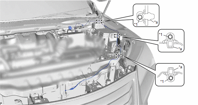
| *1 | Hood Lock Control Cable Assembly | - | - |
| *a | Clamp | - | - |
HINT:
Tape the screwdriver tip before use.
(f) Pull the hood lock control cable assembly from the engine compartment to remove it.
HINT:
- When changing the hood lock control cable assembly from type A to type B, the hood lock control lever sub-assembly must also be changed to type B.
- When changing the hood lock control cable assembly from type B to type A, the hood lock control lever sub-assembly must also be changed to type A.
.png)
| *A | Type A |
| *B | Type B |
 Installation
INSTALLATION PROCEDURE 1. INSTALL HOOD LOCK CONTROL CABLE ASSEMBLY (a) Tie the string that was passed through the grommet to the end of the hood lock control cable assembly. HINT:
When changing the ...
 Hood Support
...
Other materials:
Lexus RX (RX 350L, RX450h) 2016-2026 Repair Manual > Dynamic Torque Control Awd System: Calibration
CALIBRATION DESCRIPTION (a) When the 4WD ECU assembly is replaced with a known good one from another vehicle or the acceleration sensor (airbag ECU assembly*1 or yaw rate sensor assembly*2) is replaced, perform calibration. (b) Follow the chart to perform calibration. Part Replaced Necessary Op ...
Lexus RX (RX 350L, RX450h) 2016-2026 Owners Manual > Dynamic radar cruise
control with full-speed
range: Summary of functions
In vehicle-to-vehicle distance control mode, the vehicle automatically
accelerates,
decelerates and stops to match the speed changes of the preceding vehicle
even if the accelerator pedal is not depressed. In constant speed control mode,
the vehicle runs at a fixed speed.
Use the dynamic rad ...
Lexus RX (RX 350L, RX450h) 2016-{YEAR} Owners Manual
- For your information
- Pictorial index
- For safety and security
- Instrument cluster
- Operation of each component
- Driving
- Lexus Display Audio system
- Interior features
- Maintenance and care
- When trouble arises
- Vehicle specifications
- For owners
Lexus RX (RX 350L, RX450h) 2016-{YEAR} Repair Manual

0.0117