Lexus RX (RX 350L, RX450h) 2016-2026 Repair Manual: Removal
REMOVAL
CAUTION / NOTICE / HINT
The necessary procedures (adjustment, calibration, initialization, or registration) that must be performed after parts are removed and installed, or replaced during blind spot monitor sensor removal/installation are shown below.
Necessary Procedures After Parts Removed/Installed/Replaced| Replaced Part or Performed Procedure | Necessary Procedure | Effect/Inoperative Function when Necessary Procedure not Performed | Link |
|---|---|---|---|
|
*1: When performing learning using the Techstream.
Click here | |||
| Disconnect cable from negative battery terminal | Memorize steering angle neutral point | Lane Control System | |
| Pre-collision System | |||
| Intelligent Clearance Sonar System*1 | |||
| Parking Assist Monitor System | | ||
| Panoramic View Monitor System | | ||
| Lighting System (w/ Automatic Headlight Beam Level Control System) | | ||
| Initialize back door lock | Power Door Lock Control System | | |
| Reset back door close position | Power Back Door System (w/ Outside Door Control Switch) | | |
| Replacement of blind spot monitor sensor | Blind Spot Monitor Beam Axis Adjustment |
| |
| Rear bumper assembly (w/ Intelligent clearance sonar system) |
|
| |
PROCEDURE
1. REMOVE REAR BUMPER ASSEMBLY (w/o Rear No. 2 Seat)
Click here .gif)
2. REMOVE REAR BUMPER ASSEMBLY (w/ Rear No. 2 Seat)
Click here
3. REMOVE BLIND SPOT MONITOR SENSOR LH
| (a) Disconnect the connector. |
|
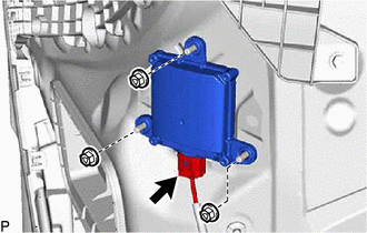
(b) Remove the 3 nuts and blind spot monitor sensor LH.
NOTICE:
Replace the blind spot monitor sensor if it has been dropped or subjected to a severe impact.
4. REMOVE BLIND SPOT MONITOR SENSOR RH
| (a) Disconnect the connector. |
|
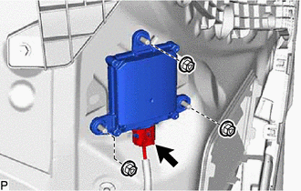
(b) Remove the 3 nuts and blind spot monitor sensor RH.
NOTICE:
Replace the blind spot monitor sensor if it has been dropped or subjected to a severe impact.
 Components
COMPONENTS ILLUSTRATION *1 BLIND SPOT MONITOR SENSOR LH *2 BLIND SPOT MONITOR SENSOR RH N*m (kgf*cm, ft.*lbf): Specified torque - - ...
 Installation
INSTALLATION CAUTION / NOTICE / HINT NOTICE:
Avoid any impact to the blind spot monitor sensor.
Do not drop the blind spot monitor sensor. If it is dropped, replace it with a new one.
HINT: ...
Other materials:
Lexus RX (RX 350L, RX450h) 2016-2026 Repair Manual > Television Camera (for Side): Installation
INSTALLATION CAUTION / NOTICE / HINT HINT:
Use the same procedure for the RH side and LH side.
The following procedure is for the LH side.
PROCEDURE 1. INSTALL SIDE TELEVISION CAMERA ASSEMBLY (a) Install the side television camera assembly with the 2 screws. 2. INSTALL OUTER MIRROR HOLE COVE ...
Lexus RX (RX 350L, RX450h) 2016-2026 Repair Manual > Smart Access System With Push-button Start (for Entry Function): Operation History List
OPERATION HISTORY LIST NOTICE:
The cause of a malfunction is stored in the RAM or EEPROM in the certification ECU (smart key ECU assembly). As the cause of a malfunction stored in the RAM will be cleared when the cable is disconnected from the negative (-) battery terminal, do not disconnect the ...
Lexus RX (RX 350L, RX450h) 2016-{YEAR} Owners Manual
- For your information
- Pictorial index
- For safety and security
- Instrument cluster
- Operation of each component
- Driving
- Lexus Display Audio system
- Interior features
- Maintenance and care
- When trouble arises
- Vehicle specifications
- For owners
Lexus RX (RX 350L, RX450h) 2016-{YEAR} Repair Manual

0.0093