Lexus RX (RX 350L, RX450h) 2016-2026 Repair Manual: Installation
INSTALLATION
PROCEDURE
1. PRECAUTION
NOTICE:
After turning the engine switch off, waiting time may be required before disconnecting the cable from the negative (-) battery terminal. Therefore, make sure to read the disconnecting the cable from the negative (-) battery terminal notices before proceeding with work.
Click here .gif)
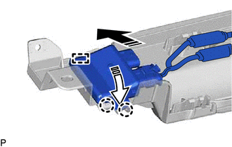
2. INSTALL KICK DOOR CONTROL SENSOR (except F-Sport without Rear No. 2 Seat)
(a) Engage the guide and 2 claws as shown in the illustration.
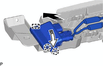
.png) | Install in this Direction (1) |
.png) | Install in this Direction (2) |
NOTICE:
- Do not subject the kick door control sensor to a strong impact or drop it.
- Do not reuse a kick door control sensor which has been subjected to a strong impact or dropped.
- Be careful not to pull the wire harness.
- Be careful not to twist the wire harness.
(b) Engage the 15 claws to install the kick door control sensor as shown in the illustration.
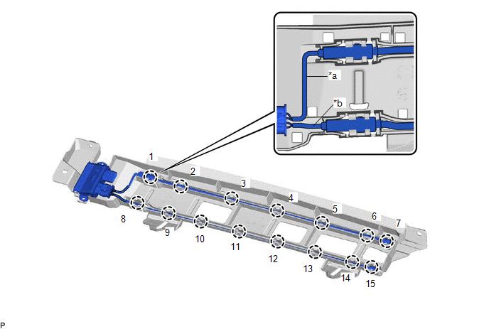
| *a | Wire (Red) | *b | Wire (Black) |
NOTICE:
Fully insert the kick door control sensor into the kick door control bracket.
HINT:
Engage each claw in the order shown in the illustration.
3. INSTALL KICK DOOR CONTROL SENSOR WITH BRACKET (except F-Sport without Rear No. 2 Seat)
(a) Engage the 4 guides as shown in the illustration.
| | Install in this Direction | - | - |
(b) Install the 2 screws.
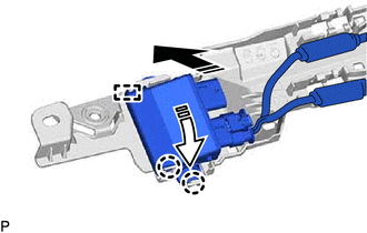
(c) Install the kick door control sensor with bracket with the 2 clips.
(d) Engage the clamp.
(e) Connect the connector.
NOTICE:
Do not touch the terminals of the kick door control sensor connector.
4. INSTALL KICK DOOR CONTROL SENSOR (for F-Sport without Rear No. 2 Seat)
(a) Engage the guide and 2 claws as shown in the illustration.
| | Install in this Direction (1) |
| | Install in this Direction (2) |
NOTICE:
- Do not subject the kick door control sensor to a strong impact or drop it.
- Do not reuse a kick door control sensor which has been subjected to a strong impact or dropped.
- Be careful not to pull the wire harness.
- Be careful not to twist the wire harness.
(b) Engage the 16 claws to install the kick door control sensor as shown in the illustration.
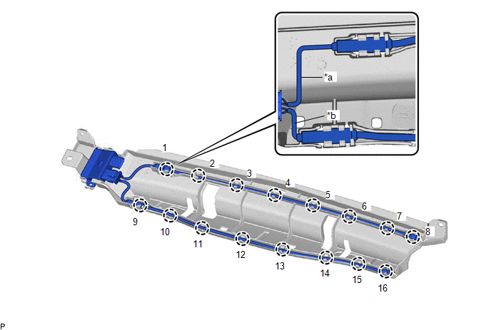
| *a | Wire (Red) | *b | Wire (Black) |
NOTICE:
Fully insert the kick door control sensor into the kick door control bracket.
HINT:
Engage each claw in the order shown in the illustration.
5. INSTALL KICK DOOR CONTROL SENSOR WITH BRACKET (for F-Sport without Rear No. 2 Seat)
(a) Engage the 4 guides as shown in the illustration.
| | Install in this Direction | - | - |
(b) Install the 2 screws.
(c) Install the kick door control sensor with bracket with the 2 clips.
(d) Engage the clamp.
(e) Connect the connector.
NOTICE:
Do not touch the terminals of the kick door control sensor connector.
6. INSTALL KICK DOOR CONTROL SENSOR (w/ Rear No. 2 Seat)
(a) Engage the guide and 2 claws as shown in the illustration.
| | Install in this Direction (1) |
| | Install in this Direction (2) |
NOTICE:
- Do not subject the kick door control sensor to a strong impact or drop it.
- Do not reuse a kick door control sensor which has been subjected to a strong impact or dropped.
- Be careful not to pull the wire harness.
- Be careful not to twist the wire harness.
(b) Engage the 16 claws to install the kick door control sensor as shown in the illustration.
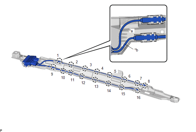
| *a | Wire (Red) | *b | Wire (Black) |
NOTICE:
Fully insert the kick door control sensor into the kick door control bracket.
HINT:
Engage each claw in the order shown in the illustration.
7. INSTALL KICK DOOR CONTROL SENSOR WITH BRACKET (w/ Rear No. 2 Seat)
(a) Engage the guide as shown in the illustration.
| | Install in this Direction | - | - |
(b) Install the 2 clips.
(c) Install the kick door control sensor with bracket with the screw.
(d) Engage the clamp.
(e) Connect the connector.
NOTICE:
Do not touch the terminals of the kick door control sensor connector.
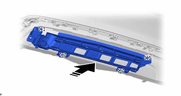
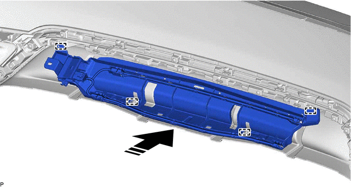
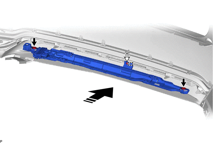
8. INSTALL REAR BUMPER ASSEMBLY (w/o Rear No. 2 Seat)
Click here
9. INSTALL REAR BUMPER ASSEMBLY (w/ Rear No. 2 Seat)
Click here
10. CONNECT CABLE TO NEGATIVE BATTERY TERMINAL
NOTICE:
When disconnecting the cable, some systems need to be initialized after the cable is reconnected.
Click here
11. INSPECT KICK DOOR CONTROL SENSOR
Click here
 Removal
REMOVAL CAUTION / NOTICE / HINT The necessary procedures (adjustment, calibration, initialization or registration) that must be performed after parts are removed and installed, or replaced during kick ...
 Power Back Door Closer Switch
ComponentsCOMPONENTS ILLUSTRATION *1 BACK DOOR CONTROL SWITCH *2 DOOR CONTROL SWITCH *3 DOOR PULL HANDLE - - RemovalREMOVAL PROCEDURE 1. REMOVE DOOR PULL HANDLE Click here 2. ...
Other materials:
Lexus RX (RX 350L, RX450h) 2016-2026 Repair Manual > Mass Air Flow Meter: Removal
REMOVAL CAUTION / NOTICE / HINT The necessary procedures (adjustment, calibration, initialization or registration) that must be performed after parts are removed and installed, or replaced during mass air flow meter sub-assembly removal/installation are shown below. Necessary Procedures After Parts ...
Lexus RX (RX 350L, RX450h) 2016-2026 Repair Manual > Roof Antenna: Installation
INSTALLATION PROCEDURE 1. INSTALL TELEPHONE ANTENNA ASSEMBLY (a) When reusing the telephone antenna assembly: (1) Install a new seal. (b) Push the telephone antenna assembly in the direction indicated by the arrow (1) shown in the illustration to engage the guide. Install in this Direction (1 ...
Lexus RX (RX 350L, RX450h) 2016-{YEAR} Owners Manual
- For your information
- Pictorial index
- For safety and security
- Instrument cluster
- Operation of each component
- Driving
- Lexus Display Audio system
- Interior features
- Maintenance and care
- When trouble arises
- Vehicle specifications
- For owners
Lexus RX (RX 350L, RX450h) 2016-{YEAR} Repair Manual

0.0104