Lexus RX (RX 350L, RX450h) 2016-2026 Repair Manual: Power Back Door Closer Switch
Components
COMPONENTS
ILLUSTRATION
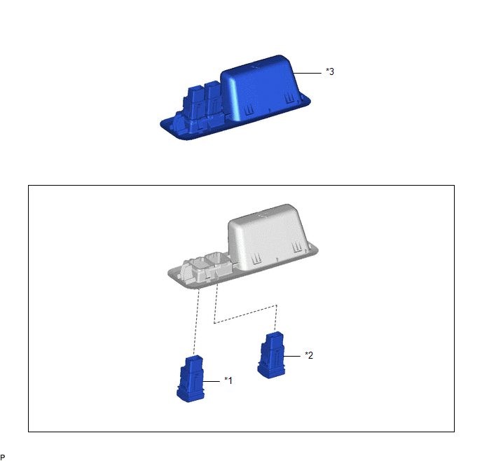
| *1 | BACK DOOR CONTROL SWITCH | *2 | DOOR CONTROL SWITCH |
| *3 | DOOR PULL HANDLE | - | - |
Removal
REMOVAL
PROCEDURE
1. REMOVE DOOR PULL HANDLE
Click here .gif)
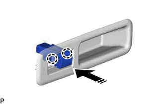
2. REMOVE BACK DOOR CONTROL SWITCH
(a) Disengage the 2 claws to remove the back door control switch as shown in the illustration.
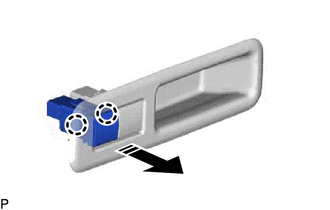
.png) | Remove in this Direction |
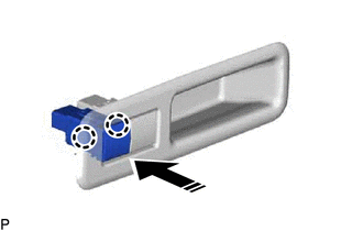
3. REMOVE DOOR CONTROL SWITCH
(a) Disengage the 2 claws to remove the door control switch as shown in the illustration.
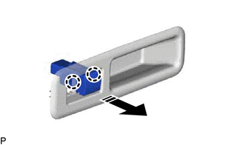
| | Remove in this Direction |
Inspection
INSPECTION
PROCEDURE
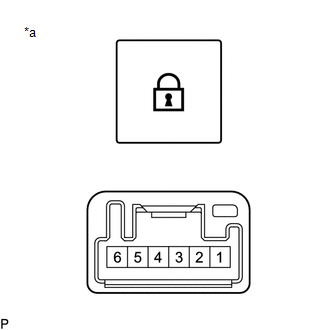
1. INSPECT BACK DOOR CONTROL SWITCH
(a) Check the switch.
| (1) Measure the resistance according to the value(s) in the table below. Standard Resistance:
If the result is not as specified, replace the back door control switch. |
|
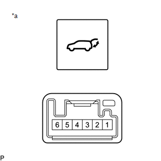
(b) Check that the switch illuminates.
(1) Apply battery voltage to the switch connector and check that the back door control switch illuminates.
OK:
| Battery Connection | Specified Condition |
|---|---|
| Battery positive (+) → Terminal 6 Battery negative (-) → Terminal 1 | Illumination illuminates |
If the result is not as specified, replace the back door control switch.
2. INSPECT DOOR CONTROL SWITCH
(a) Check the switch.
| (1) Measure the resistance according to the value(s) in the table below. Standard Resistance:
If the result is not as specified, replace the door control switch. |
|
(b) Check the switch illumination.
(1) Apply battery voltage to the switch connector and check that the door control switch illuminates.
OK:
| Battery Connection | Specified Condition |
|---|---|
| Battery positive (+) → Terminal 6 Battery negative (-) → Terminal 1 | Illumination illuminates |
If the result is not as specified, replace the door control switch.
Installation
INSTALLATION
PROCEDURE
1. INSTALL DOOR CONTROL SWITCH
(a) Engage the 2 claws to install the door control switch as shown in the illustration.
.png) | Install in this Direction |
2. INSTALL BACK DOOR CONTROL SWITCH
(a) Engage the 2 claws to install the back door control switch as shown in the illustration.
| | Install in this Direction |
3. INSTALL DOOR PULL HANDLE
Click here .gif)
 Installation
INSTALLATION PROCEDURE 1. PRECAUTION NOTICE: After turning the engine switch off, waiting time may be required before disconnecting the cable from the negative (-) battery terminal. Therefore, make su ...

Other materials:
Lexus RX (RX 350L, RX450h) 2016-2026 Repair Manual > Airbag System: Short in Knee Airbag (D Side) Squib Circuit (B1860-B1863)
DESCRIPTION The driver side knee airbag squib circuit consists of the airbag sensor assembly and lower No. 1 instrument panel airbag assembly. The airbag sensor assembly uses this circuit to deploy the airbag when deployment conditions are met. These DTCs are stored when a malfunction is detected in ...
Lexus RX (RX 350L, RX450h) 2016-2026 Repair Manual > Air Conditioning Pressure Sensor: On-vehicle Inspection
ON-VEHICLE INSPECTION PROCEDURE 1. INSPECT AIR CONDITIONER PRESSURE SENSOR (a) Check the wire harness. (1) Disconnect the A9 air conditioner pressure sensor connector. (2) Disconnect the J42 air conditioning amplifier assembly connector. (3) Measure the resistance according to the value(s) in the ta ...
Lexus RX (RX 350L, RX450h) 2016-{YEAR} Owners Manual
- For your information
- Pictorial index
- For safety and security
- Instrument cluster
- Operation of each component
- Driving
- Lexus Display Audio system
- Interior features
- Maintenance and care
- When trouble arises
- Vehicle specifications
- For owners
Lexus RX (RX 350L, RX450h) 2016-{YEAR} Repair Manual

0.0089