Lexus RX (RX 350L, RX450h) 2016-2026 Repair Manual: Terminals Of Ecu
TERMINALS OF ECU
CHECK MULTIPLEX NETWORK DOOR ECU
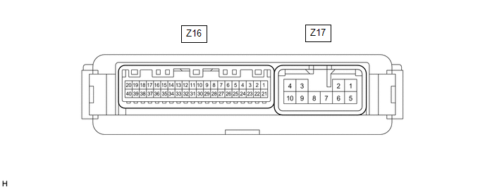
(a) Disconnect the Z16 and Z17 multiplex network door ECU connectors.
(b) Measure the voltage and resistance according to the value(s) in the table below.
HINT:
Measure the values on the wire harness side with the connector disconnected.
| Terminal No. (Symbol) | Wiring Color | Terminal Description | Condition | Specified Condition |
|---|---|---|---|---|
| Z16-20 (ECUB) - Body ground | GR - Body ground | Battery power supply | Always | 11 to 14 V |
| Z16-18 (IG) - Body ground | P - Body ground | IG power supply | Engine switch on (IG) | 11 to 14 V |
| Engine switch off | Below 1 V | |||
| Z17-1 (B) - Body ground | Y - Body ground | Battery power supply | Always | 11 to 14 V |
| Z17-10 (GND) - Body ground | W-B - Body ground | Body ground | Always | Below 1 Ω |
(c) Reconnect the Z16 and Z17 multiplex network door ECU connectors.
(d) Measure the voltage and check for pulses according to the value(s) in the table below.
| Terminal No. (Symbol) | Wiring Color | Terminal Description | Condition | Specified Condition |
|---|---|---|---|---|
| Z16-1 (DS1) - Body ground | Y - Body ground | Power back door unit assembly set LH (door sensor) signal | Power back door not operating | 7 V or higher |
| Power back door operating | Pulse generation (See waveform 1) | |||
| Z16-2 (DS2) - Body ground | W - Body ground | Power back door unit assembly set LH (door sensor) signal | Power back door not operating | 7 V or higher |
| Power back door operating | Pulse generation (See waveform 2) | |||
| Z16-3 (DS12) - Body ground | Y - Body ground | Power back door unit assembly set RH (door sensor) signal | Power back door not operating | 7 V or higher |
| Power back door operating | Pulse generation (See waveform 1) | |||
| Z16-4 (DS22) - Body ground | W - Body ground | Power back door unit assembly set RH (door sensor) signal | Power back door not operating | 7 V or higher |
| Power back door operating | Pulse generation (See waveform 2) | |||
| Z16-5 (DSV2) - Body ground | L - Body ground | Power back door unit assembly set RH (door sensor) power supply | Always | 7 V or higher |
| Z16-6 (OSR) - Z16-24 (OSE) | B - R | Power back door sensor assembly RH signal | Power back door sensor assembly RH not pressed | 4 to 6 V |
| Power back door sensor assembly RH pressed | Below 1 V | |||
| Z16-8 (BDDN) - Body ground | W - Body ground | Back door control switch signal | Back door control switch on | Below 1 V |
| Back door control switch off | Pulse generation | |||
| Z16-10 (CLSW) - Body ground | R - Body ground | Door control switch signal | Door control switch on | Below 1 V |
| Door control switch off | 11 to 14 V | |||
| Z16-14 (KSIN) - Body ground* | L - Body ground | Kick detection signal | Kick door control sensor not detecting a foot → detecting a foot | Pulse generation (See waveform 3) |
| Z16-16 (BZR+) - Body ground | GR - Body ground | Wireless door lock buzzer signal | Power back door warning buzzer sounding | Pulse generation |
| Power back door warning buzzer not sounding | Below 1 V | |||
| Z16-19 (DSG2) - Body ground | P - Body ground | Power back door unit assembly set RH (door sensor) ground | Always | Below 1 V |
| Z16-21 (DSG) - Body ground | P - Body ground | Power back door unit assembly set LH (door sensor) ground | Always | Below 1 V |
| Z16-25 (DSV) - Body ground | L - Body ground | Power back door unit assembly set LH (door sensor) power supply | Always | 7 V or higher |
| Z16-26 (OSL) - Z16-24 (OSE) | B - R | Power back door sensor assembly LH signal | Power back door sensor assembly LH not pressed | 4 to 6 V |
| Power back door sensor assembly LH pressed | Below 1 V | |||
| Z17-4 (DC+) - Z17-3 (DC-) | W - B | Back door lock assembly (back door lock motor) circuit | Back door lock motor operating | 11 to 14 V |
| Back door lock motor not operating | Below 1 V |
- *: w/ Hands Free Power Back Door
(1) Using an oscilloscope, check waveform 1.
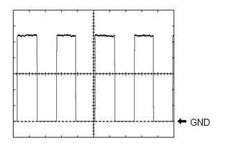 Waveform 1 (Reference)
 | Item | Condition |
|---|---|
| Tester Connection |
|
| Tool setting | 2 V/DIV., 2 ms/DIV. |
| Vehicle condition | Power back door operating |
HINT:
The period changes in accordance to the speed at which the power back door is opened and closed.
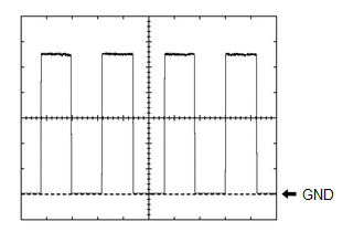
(2) Using an oscilloscope, check waveform 2.
Waveform 2 (Reference)| Item | Condition |
|---|---|
| Tester Connection |
|
| Tool setting | 2 V/DIV., 2 ms/DIV. |
| Vehicle condition | Power back door operating |
HINT:
The period changes in accordance to the speed at which the power back door is opened and closed.
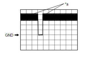
(3) Using an oscilloscope, check waveform 3.
Waveform 3 (Reference)| Item | Condition |
|---|---|
| Tester Connection | Z16-14 (KSIN) - Body ground |
| Tool setting | 2 V/DIV., 50 ms/DIV. |
| Vehicle condition | Kick door control sensor not detecting a foot → detecting a foot |
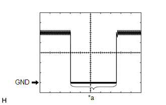
| *a | Kick detection signal |
CHECK CERTIFICATION ECU (SMART KEY ECU ASSEMBLY)
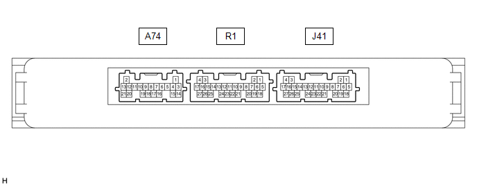
(a) Disconnect the J41 certification ECU (smart key ECU assembly) connector.
(b) Measure the voltage and resistance according to the value(s) in the table below.
HINT:
Measure the values on the wire harness side with the connector disconnected.
| Terminal No. (Symbol) | Wiring Color | Terminal Description | Condition | Specified Condition |
|---|---|---|---|---|
| J41-4 (+B) - Body ground | V - Body ground | Battery power supply | Always | 11 to 14 V |
| J41-18 (E) - Body ground | W-B - Body ground | Body ground | Always | Below 1 Ω |
(c) Reconnect the J41 certification ECU (smart key ECU assembly) connector.
(d) Measure the waveform according to the value(s) in the table below.
| Terminal No. (Symbol) | Wiring Color | Terminal Description | Condition | Specified Condition |
|---|---|---|---|---|
| R1-26 (TSW5) - J41-18 (E) | G - W-B | Back door opener switch assembly (open switch) signal | Back door opener switch assembly (open switch) off → on | Pulse generation (See waveform 1) |
(1) Using an oscilloscope, check the waveform.
| *a | Checking for switch on signal at short intervals |
| Item | Content |
|---|---|
| Terminal No. (Symbol) | R1-26 (TSW5) - J41-18 (E) |
| Tool Setting | 2 V/DIV., 500 ms/DIV. |
| Condition | Back door opener switch assembly (open switch) off → on |
CHECK MAIN BODY ECU (MULTIPLEX NETWORK BODY ECU) AND INSTRUMENT PANEL JUNCTION BLOCK ASSEMBLY
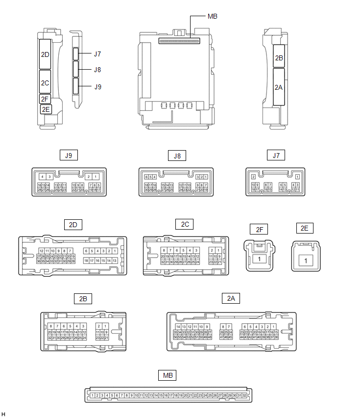
(a) Remove the main body ECU (multiplex network body ECU) from the instrument panel junction block assembly.
Click here .gif)
(b) Reconnect the instrument panel junction block assembly connectors.
(c) Measure the resistance and voltage according to the value(s) in the table below.
HINT:
Measure the values on the wire harness side with the connector disconnected.
| Terminal No. (Symbol) | Wiring Color | Terminal Description | Condition | Specified Condition |
|---|---|---|---|---|
| MB-31 (BECU) - Body ground | - | Battery power supply | Always | 11 to 14 V |
| MB-32 (IG) - Body ground | - | Ignition power supply (IG signal) | Engine switch off | Below 1 V |
| Engine switch on (IG) | 11 to 14 V | |||
| MB-30 (ACC) - Body ground | - | Ignition power supply (ACC signal) | Engine switch off | Below 1 V |
| Engine switch on (ACC) | 11 to 14 V | |||
| MB-11 (GND1) - Body ground | - | Ground | Always | Below 1 Ω |
(d) Install the main body ECU (multiplex network body ECU) to instrument panel junction block assembly.
Click here
(e) Measure the voltage and check for pulses according to the value(s) in the table below.
| Terminal No. (Symbol) | Wiring Color | Terminal Description | Condition | Specified Condition |
|---|---|---|---|---|
| J9-5 (PBDS) - Body ground | R - Body ground | Power back door switch (integration control and panel assembly) signal | Power back door switch (integration control and panel assembly) off | Pulse generation |
| Power back door switch (integration control and panel assembly) on | Below 1 V | |||
| 2C-29 (BZR) - Body ground | P - Body ground | Wireless door lock buzzer signal | Wireless door lock buzzer not operating | Below 1 V |
| Wireless door lock buzzer operating | Pulse generation |
 Freeze Frame Data
FREEZE FRAME DATA FREEZE FRAME DATA (a) Whenever a DTC is detected, the multiplex network door ECU stores the current vehicle state as Freeze Frame Data. CHECK FREEZE FRAME DATA (a) Connect the Techst ...
 Data List / Active Test
DATA LIST / ACTIVE TEST DATA LIST NOTICE: In the table below, the values listed under "Normal Condition" are reference values. Do not depend solely on these reference values when deciding whether a pa ...
Other materials:
Lexus RX (RX 350L, RX450h) 2016-2026 Owners Manual > Bluetooth Phone: Bluetooth phone
settings
You can adjust the hands-free system to your desired settings.
"Phone Settings" screen
Go to "Phone Settings": "MENU" button → "Setup" → "Phone"
Register and connect a Bluetooth
device
Adjust the call volume and message
readout volume
Change display settings
Change the contact/c ...
Lexus RX (RX 350L, RX450h) 2016-2026 Repair Manual > Pre-collision System: Customize Parameters
CUSTOMIZE PARAMETERS NOTICE:
When the customer requests a change in a function, first make sure that the function can be customized.
Be sure to make a note of the current settings before customizing.
When troubleshooting a function, first make sure that the function is set to the default sett ...
Lexus RX (RX 350L, RX450h) 2016-{YEAR} Owners Manual
- For your information
- Pictorial index
- For safety and security
- Instrument cluster
- Operation of each component
- Driving
- Lexus Display Audio system
- Interior features
- Maintenance and care
- When trouble arises
- Vehicle specifications
- For owners
Lexus RX (RX 350L, RX450h) 2016-{YEAR} Repair Manual

0.0093