Lexus RX (RX 350L, RX450h) 2016-2026 Repair Manual: PBD Unit Pulse Sensor RH Circuit (B2227)
DESCRIPTION
This DTC is stored when the multiplex network door ECU detects an error in the power back door unit assembly set RH pulse signal.
| DTC No. | Detection Item | DTC Detection Condition | Trouble Area |
|---|---|---|---|
| B2227 | PBD Unit Pulse Sensor RH Circuit | Multiplex network door ECU detects power back door unit assembly set RH pulse malfunction |
|
WIRING DIAGRAM
.png)
CAUTION / NOTICE / HINT
NOTICE:
If the multiplex network door ECU has been removed and installed or replaced, or if any of the connectors have been disconnected, initialize the power back door system.
Click here .gif)
PROCEDURE
| 1. | CHECK FOR DTC |
(a) Connect the Techstream to the DLC3.
(b) Turn the engine switch on (IG).
(c) Turn the Techstream on.
(d) Enter the following menus: Body Electrical / Back Door / Trouble Codes.
(e) Clear the DTCs.
Body Electrical > Back Door > Clear DTCs(f) Recheck for DTCs.
Body Electrical > Back Door > Trouble CodesOK:
DTC B2227 is not output.
| OK | .gif) | USE SIMULATION METHOD TO CHECK |
|
.gif)
| 2. | CHECK HARNESS AND CONNECTOR (MULTIPLEX NETWORK DOOR ECU - POWER BACK DOOR UNIT ASSEMBLY SET RH) |
(a) Disconnect the Z16 multiplex network door ECU connector.
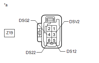
(b) Disconnect the Z19 power back door unit assembly set RH connector.
(c) Measure the resistance according to the value(s) in the table below.
Standard Resistance:
| Tester Connection | Condition | Specified Condition |
|---|---|---|
| Z16-19 (DSG2) - Z19-4 (DSG2) | Always | Below 1 Ω |
| Z16-5 (DSV2) - Z19-3 (DSV2) | Always | Below 1 Ω |
| Z16-4 (DS22) - Z19-6 (DS22) | Always | Below 1 Ω |
| Z16-3 (DS12) - Z19-5 (DS12) | Always | Below 1 Ω |
| Z16-19 (DSG2) or Z19-4 (DSG2) - Body ground | Always | 10 kΩ or higher |
| Z16-5 (DSV2) or Z19-3 (DSV2) - Body ground | Always | 10 kΩ or higher |
| Z16-4 (DS22) or Z19-6 (DS22) - Body ground | Always | 10 kΩ or higher |
| Z16-3 (DS12) or Z19-5 (DS12) - Body ground | Always | 10 kΩ or higher |
| NG | | REPAIR OR REPLACE HARNESS OR CONNECTOR |
|
| 3. | CHECK MULTIPLEX NETWORK DOOR ECU |
(a) Reconnect the Z16 multiplex network door ECU connector.
| (b) Measure the resistance according to the value(s) in the table below. Standard Resistance:
|
|
(c) Measure the voltage according to the value(s) in the table below.
Standard Voltage:
| Tester Connection | Condition | Specified Condition |
|---|---|---|
| Z19-5 (DS12) - Body ground | Always | 7 V or higher |
| Z19-6 (DS22) - Body ground | Always | 7 V or higher |
| Z19-3 (DSV2) - Body ground | Always | 7 V or higher |
| NG | | REPLACE MULTIPLEX NETWORK DOOR ECU |
|
| 4. | CHECK POWER BACK DOOR UNIT ASSEMBLY SET RH |
(a) Disconnect the Z19 power back door unit assembly set RH connector.
(b) Using an oscilloscope, check the waveform of each terminal from the rear of the multiplex network door ECU Z16 connector.
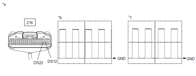
| *a | Component with harness connected (Multiplex Network Door ECU) | *b | Waveform (CH1) |
| *c | Waveform (CH2) | - | - |
Measurement Condition:
| Item | Condition |
|---|---|
| Tester Connection |
|
| Tool setting | 2 V/DIV., 2 ms/DIV. |
| Vehicle condition | Open and close the back door by hand. |
HINT:
The period changes in accordance to the speed at which the back door is opened and closed by hand.
OK:
The waveform displayed is as shown in the illustration.
| OK | | REPLACE MULTIPLEX NETWORK DOOR ECU |
| NG | | REPLACE POWER BACK DOOR UNIT ASSEMBLY SET RH |
 PBD Unit Pulse Sensor LH Circuit (B2226)
DESCRIPTION This DTC is stored when the multiplex network door ECU detects an error in the power back door unit assembly set LH pulse signal. DTC No. Detection Item DTC Detection Condition Tr ...
 PBD Touch Sensor LH Circuit (B222A)
DESCRIPTION This DTC is stored when the multiplex network door ECU detects a malfunction in the power back door sensor assembly LH touch sensor. DTC No. Detection Item DTC Detection Condition ...
Other materials:
Lexus RX (RX 350L, RX450h) 2016-2026 Repair Manual > Wiper / Washer: Rain Sensor
ComponentsCOMPONENTS ILLUSTRATION *1 RAIN SENSOR *2 RAIN SENSOR COVER *3 RAIN SENSOR TAPE - - On-vehicle InspectionON-VEHICLE INSPECTION PROCEDURE 1. INSPECT RAIN SENSOR (a) Disconnect the U3 rain sensor connector. *a Front view of wire harness connector (to ...
Lexus RX (RX 350L, RX450h) 2016-2026 Repair Manual > Telephone And Gps Antenna (for Roof Side): Components
COMPONENTS ILLUSTRATION *1 TELEPHONE AND GPS ANTENNA ASSEMBLY *2 TELEPHONE AND GPS ANTENNA ASSEMBLY WITH COVER *3 COVER *4 WASHER AND HOLDER *5 SEAL *6 TELEPHONE ANTENNA HOUSING N*m (kgf*cm, ft.*lbf): Specified torque ● Non-reusable part ...
Lexus RX (RX 350L, RX450h) 2016-{YEAR} Owners Manual
- For your information
- Pictorial index
- For safety and security
- Instrument cluster
- Operation of each component
- Driving
- Lexus Display Audio system
- Interior features
- Maintenance and care
- When trouble arises
- Vehicle specifications
- For owners
Lexus RX (RX 350L, RX450h) 2016-{YEAR} Repair Manual

0.0103