Lexus RX (RX 350L, RX450h) 2016-2026 Repair Manual: Removal
REMOVAL
CAUTION / NOTICE / HINT
The necessary procedures (adjustment, calibration, initialization, or registration) that must be performed after parts are removed and installed, or replaced during front bumper assembly removal/installation are shown below.
Necessary Procedures After Parts Removed/Installed/Replaced| Replaced Part or Performed Procedures | Necessary Procedures | Effect/Inoperative Function When Necessary Procedures are not Performed | Link |
|---|---|---|---|
| w/ Panoramic View Monitor System
| Front television camera view adjustment | Panoramic View Monitor System | |
| w/ Intelligent Clearance Sonar System
|
|
| |
HINT:
When the front bumper is damaged or deformed due to an accident or contact with other objects, etc., or the bumper installation area on the body is repaired, it is necessary to perform millimeter wave radar sensor adjustment.
Click here .gif)
PROCEDURE
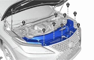
1. REMOVE COOL AIR INTAKE DUCT SEAL
| (a) Remove the 9 clips and cool air intake duct seal. |
|
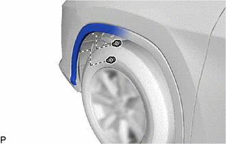
2. DISCONNECT FRONT FENDER MOULDING SUB-ASSEMBLY LH
| (a) Remove the 2 clips. |
|
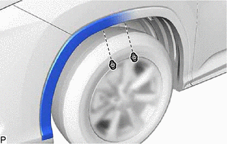
| (b) Remove the 2 clips. |
|
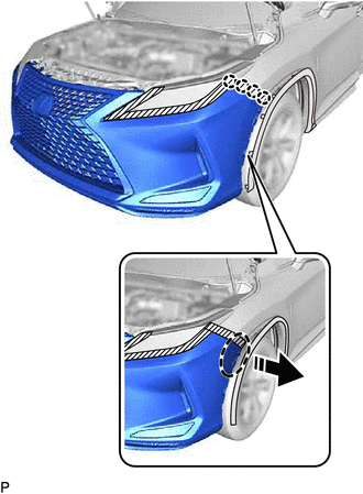
(c) Pull back the edge of the front fender splash shield sub-assembly LH and disengage the 5 claws by pushing the area indicated by the arrow in the illustration with a finger.
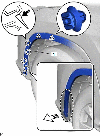
| *1 | Front Fender Splash Shield Sub-assembly LH |
.png) | Place Hand Here |
.png) | Remove in this Direction (1) |
.png) | Remove in this Direction (2) |
NOTICE:
- Do not apply excessive force when pulling back the front fender splash shield sub-assembly LH.
- To avoid damaging the claws, do not forcibly pull the front fender moulding sub-assembly LH.
(d) Disengage the 2 clips and disconnect the front fender moulding sub-assembly LH.
3. DISCONNECT FRONT FENDER MOULDING SUB-ASSEMBLY RH
HINT:
Use the same procedure as for the LH side.
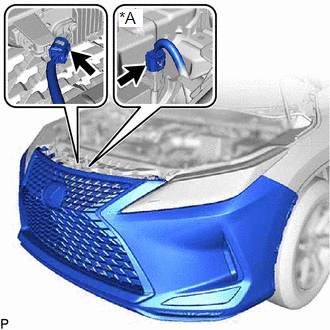
4. REMOVE FRONT BUMPER ASSEMBLY
| (a) Disconnect each connector. |
|
(b) Apply protective tape around the front bumper assembly.
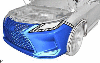
.png) | Protective Tape |
HINT:
Use the same procedure for the RH side and LH side.
| (c) Remove each clip. HINT: Use the same procedure for the RH side and LH side. |
|
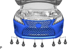
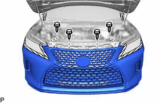
| (d) Remove the 8 screws. |
|
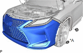
(e) Disengage the 4 claws as shown in the illustration.
| | Place Hand Here |
| | Remove in this Direction |
HINT:
Use the same procedure for the RH side and LH side.
(f) w/ Intuitive Parking Assist System or Fog Light:
(1) Pull back the side of the front bumper assembly, disconnect each connector.
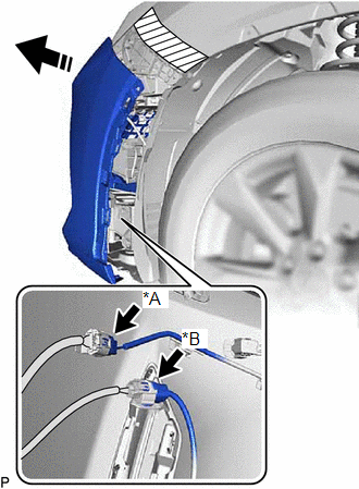
| *A | w/ Intuitive Parking Assist System |
| *B | w/ Fog Light |
| | Remove in this Direction |
NOTICE:
Do not apply excessive force when pulling back the front bumper assembly.
HINT:
Use the same procedure for the RH side and LH side.
(g) w/ Headlight Cleaner System:
(1) Pull back the side of the front bumper assembly and disconnect the headlight cleaner hose.
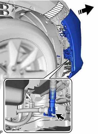
| | Remove in this Direction |
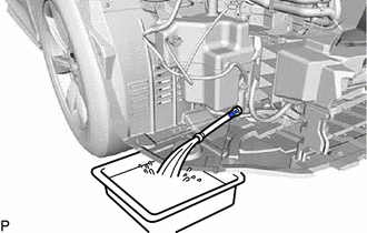
| (2) Drain the washer fluid. HINT: Use a container to collect the washer fluid. |
|
| (h) Remove the 4 bolts. |
|
(i) Remove the 2 clips and front bumper assembly as shown in the illustration.
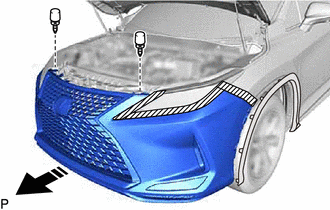
| | Remove in this Direction |
 Installation
INSTALLATION CAUTION / NOTICE / HINT HINT: When the front bumper is damaged or deformed due to an accident or contact with other objects, etc., or the bumper installation area on the body is repaired, ...
 Disassembly
DISASSEMBLY PROCEDURE 1. REMOVE FRONT BUMPER ARM HOLE COVER LH (for Type A) (a) Remove the screw and clip. Screw Clip (b) Disengage the 3 guides to remove the front bumper arm hole ...
Other materials:
Lexus RX (RX 350L, RX450h) 2016-2026 Repair Manual > Occupant Classification System: Occupant Classification ECU Malfunction (B1795)
DESCRIPTION DTC B1795 is stored when a malfunction is detected in the occupant detection ECU. DTC No. Detection Item DTC Detection Condition Trouble Area B1795 Occupant Classification ECU Malfunction Occupant detection ECU malfunction Occupant detection ECU CAUTION / NOTICE / H ...
Lexus RX (RX 350L, RX450h) 2016-2026 Repair Manual > Audio And Visual System (for 12.3 Inch Display): Radio Receiver Power Source Circuit
DESCRIPTION This is the power source circuit to operate the radio receiver assembly. WIRING DIAGRAM CAUTION / NOTICE / HINT NOTICE: Inspect the fuses for circuits related to this system before performing the following procedure. PROCEDURE 1. CHECK HARNESS AND CONNECTOR (RADIO RECEIVER ASSEMBL ...
Lexus RX (RX 350L, RX450h) 2016-{YEAR} Owners Manual
- For your information
- Pictorial index
- For safety and security
- Instrument cluster
- Operation of each component
- Driving
- Lexus Display Audio system
- Interior features
- Maintenance and care
- When trouble arises
- Vehicle specifications
- For owners
Lexus RX (RX 350L, RX450h) 2016-{YEAR} Repair Manual

0.0095