Lexus RX (RX 350L, RX450h) 2016-2026 Repair Manual: Reassembly
REASSEMBLY
PROCEDURE
1. INSTALL CENTER STOP LIGHT ASSEMBLY
Click here .gif)
2. INSTALL NO. 2 REAR SPOILER SEAL
HINT:
When installing the No. 2 rear spoiler seal, heat the rear spoiler using a heat light.
Heating Temperature| Item | Temperature |
|---|---|
| Rear Spoiler | 20 to 30°C (68 to 86°F) |
CAUTION:
- Do not touch the heat light and heated parts, touching the heat light may result in burns.
- Touching heated parts for a long time may result in burns.
.png)
| *a | Heated Part |
| *b | Heat Light |
NOTICE:
Do not heat the rear spoiler excessively.
(a) Clean the rear spoiler surface.
(1) Using a heat light, heat the rear spoiler surface.
(2) Remove the double-sided tape from the rear spoiler.
(3) Wipe off any tape adhesive residue with cleaner.
(b) Using a heat light, heat the rear spoiler.
(c) Remove the release paper from the 2 new No. 2 rear spoiler seals.
HINT:
After removing the release paper, keep the exposed adhesive free from foreign matter.
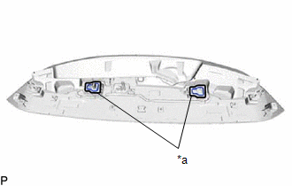
| (d) Install the 2 No. 2 rear spoiler seals as shown in the illustration. HINT: Apply the No. 2 rear spoiler seal along the line marked on the rear spoiler. |
|
3. INSTALL REAR SPOILER SEAL
HINT:
When installing the rear spoiler seal, heat the rear spoiler using a heat light.
Heating Temperature| Item | Temperature |
|---|---|
| Rear Spoiler | 20 to 30°C (68 to 86°F) |
CAUTION:
- Do not touch the heat light and heated parts, touching the heat light may result in burns.
- Touching heated parts for a long time may result in burns.
| *a | Heated Part |
| *b | Heat Light |
NOTICE:
Do not heat the rear spoiler excessively.
(a) Clean the rear spoiler surface.
(1) Using a heat light, heat the rear spoiler surface.
(2) Remove the double-sided tape from the rear spoiler.
(3) Wipe off any tape adhesive residue with cleaner.
(b) Using a heat light, heat the rear spoiler.
(c) Remove the release paper from a new rear spoiler seal.
HINT:
After removing the release paper, keep the exposed adhesive free from foreign matter.
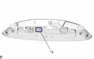
| (d) Install the rear spoiler seal as shown in the illustration. HINT: Apply the rear spoiler seal along the line marked on the rear spoiler. |
|
4. INSTALL NO. 2 REAR SPOILER PROTECTOR (except TMMC Made)
HINT:
When installing the No. 2 rear spoiler protector, heat the rear spoiler using a heat light.
Heating Temperature| Item | Temperature |
|---|---|
| Rear Spoiler | 20 to 30°C (68 to 86°F) |
CAUTION:
- Do not touch the heat light and heated parts, touching the heat light may result in burns.
- Touching heated parts for a long time may result in burns.
| *a | Heated Part |
| *b | Heat Light |
NOTICE:
Do not heat the rear spoiler excessively.
(a) Clean the rear spoiler surface.
(1) Using a heat light, heat the rear spoiler surface.
(2) Remove the double-sided tape from the rear spoiler.
(3) Wipe off any tape adhesive residue with cleaner.
(b) Using a heat light, heat the rear spoiler.
(c) Remove the release paper from the 3 new No. 2 rear spoiler protectors.
HINT:
After removing the release paper, keep the exposed adhesive free from foreign matter.
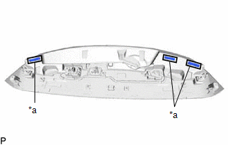
| (d) Install the 3 No. 2 rear spoiler protectors as shown in the illustration. HINT: Apply the No. 2 rear spoiler protector along the line marked on the rear spoiler. |
|
5. INSTALL NO. 1 REAR SPOILER PROTECTOR (except TMMC Made)
HINT:
When installing the No. 1 rear spoiler protector, heat the rear spoiler using a heat light.
Heating Temperature| Item | Temperature |
|---|---|
| Rear Spoiler | 20 to 30°C (68 to 86°F) |
CAUTION:
- Do not touch the heat light and heated parts, touching the heat light may result in burns.
- Touching heated parts for a long time may result in burns.
| *a | Heated Part |
| *b | Heat Light |
NOTICE:
Do not heat the rear spoiler excessively.
(a) Clean the rear spoiler surface.
(1) Using a heat light, heat the rear spoiler surface.
(2) Remove the double-sided tape from the rear spoiler.
(3) Wipe off any tape adhesive residue with cleaner.
(b) Using a heat light, heat the rear spoiler.
(c) Remove the release paper from the 5 new No. 1 rear spoiler protectors.
HINT:
After removing the release paper, keep the exposed adhesive free from foreign matter.
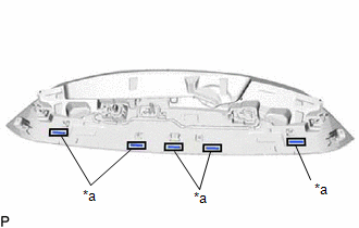
| (d) Install the 5 No. 1 rear spoiler protectors as shown in the illustration. HINT: Apply the No. 1 rear spoiler protector along the line marked on the rear spoiler. |
|
 Installation
INSTALLATION PROCEDURE 1. INSTALL SIDE REAR SPOILER PROTECTOR SUB-ASSEMBLY LH (a) Install 3 new clips to the side rear spoiler protector sub-assembly LH. (b) Engage the 4 clips as shown in the illustr ...
 Removal
REMOVAL PROCEDURE 1. REMOVE BACK WINDOW UPPER PANEL TRIM (w/o Rear No. 2 Seat) Click here 2. REMOVE BACK WINDOW UPPER PANEL TRIM (w/ Rear No. 2 Seat) Click here 3. REMOVE REAR SPOILER SUB-ASSEMB ...
Other materials:
Lexus RX (RX 350L, RX450h) 2016-2026 Repair Manual > Canister: Installation
INSTALLATION PROCEDURE 1. INSTALL CHARCOAL CANISTER LEAK DETECTION PUMP SUB-ASSEMBLY HINT: Only perform this procedure when replacement of the charcoal canister leak detection pump sub-assembly is necessary. (a) Engage the 2 claws to install a new charcoal canister leak detection pump sub-assembl ...
Lexus RX (RX 350L, RX450h) 2016-2026 Repair Manual > Audio And Visual System (for 12.3 Inch Display): Display Disconnected (B15D6)
DESCRIPTION The multi-display assembly and radio receiver assembly are connected by AVC-LAN communication lines. This DTC is stored when an AVC-LAN communication error occurs between the multi-display assembly and radio receiver assembly. DTC No. Detection Item DTC Detection Condition Troub ...
Lexus RX (RX 350L, RX450h) 2016-{YEAR} Owners Manual
- For your information
- Pictorial index
- For safety and security
- Instrument cluster
- Operation of each component
- Driving
- Lexus Display Audio system
- Interior features
- Maintenance and care
- When trouble arises
- Vehicle specifications
- For owners
Lexus RX (RX 350L, RX450h) 2016-{YEAR} Repair Manual

0.0126