Lexus RX (RX 350L, RX450h) 2016-2026 Repair Manual: Removal
REMOVAL
CAUTION / NOTICE / HINT
The necessary procedures (adjustment, calibration, initialization or registration) that must be performed after parts are removed and installed, or replaced during headlight assembly removal/installation are shown below.
Necessary Procedure After Parts Removed/Installed/Replaced| Replaced Part or Performed Procedure | Necessary Procedure | Effect/Inoperative Function when Necessary Procedure not Performed | Link |
|---|---|---|---|
| Front bumper assembly | Front television camera view adjustment | Panoramic view monitor system | |
| Front bumper assembly (w/ Intelligent clearance sonar system) |
|
| |
| No. 1 headlight ECU sub-assembly LH |
| Lighting System (w/ Automatic Headlight Beam Level Control System) | |
NOTICE:
If the headlight assembly RH is replaced with a new one, vehicle information registration and initialization are not necessary.
HINT:
- Use the same procedure for the RH side and LH side.
- The following procedure is for the LH side.
PROCEDURE
1. REMOVE FRONT BUMPER ASSEMBLY
Click here .gif)
2. DISCONNECT FRONT FENDER REINFORCEMENT SUB-ASSEMBLY TOP
| (a) Remove the center hood cushion and clip. |
|
(b) Disengage the 2 claws and 2 guides to disconnect the front fender reinforcement sub-assembly top.
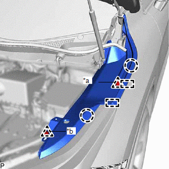
3. REMOVE HEADLIGHT ASSEMBLY
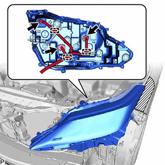
(a) Apply protective tape around the headlight assembly as shown in the illustration.
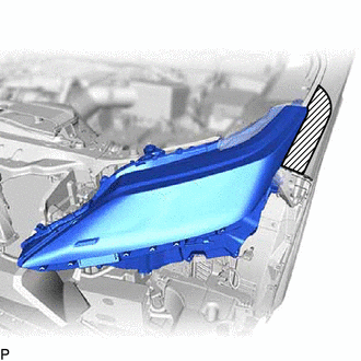
.png) | Protective Tape |
(b) Remove the 2 bolts <A> and bolt <B>.
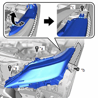
| *a | Bolt <A> |
| *b | Bolt <B> |
| *c | Screw |
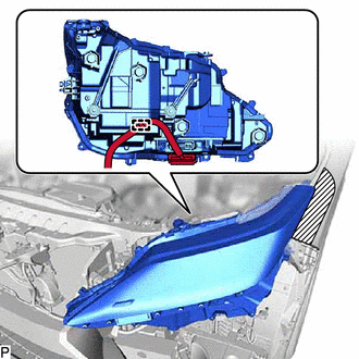
.png) | Pull Back in this Direction |
(c) Pull back the front fender reinforcement sub-assembly top and remove the screw as shown in the illustration.
(d) Disengage the guide to separate the headlight assembly as shown in the illustration.
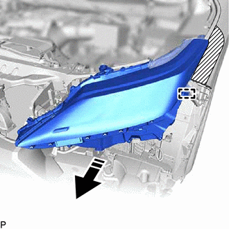
| | Separate in this Direction |
(e) w/o Automatic Headlight Beam Level Control System:
| (1) Disengage the 3 clamps. |
|
(2) Disconnect the 3 connectors to remove the headlight assembly.
(f) w/ Automatic Headlight Beam Level Control System:
(1) Disengage the claw, pull down the connector lock lever as shown in the illustration and disconnect the connector.
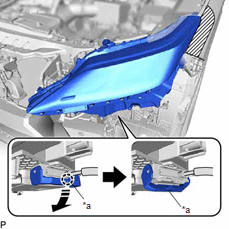
| *a | Connector Lock Lever |
| | Disconnect in this Direction |
| (2) Disengage the clamp to remove the headlight assembly. |
|
 Disassembly
DISASSEMBLY CAUTION / NOTICE / HINT HINT:
Use the same procedure for the RH side and LH side.
The following procedure is for the LH side.
PROCEDURE 1. REMOVE FRONT TURN SIGNAL LIGHT BULB (for ...
 Adjustment
ADJUSTMENT CAUTION / NOTICE / HINT HINT:
Use the same procedure for the RH side and LH side.
The following procedure is for the LH side.
PROCEDURE 1. PREPARE VEHICLE FOR HEADLIGHT AIM ADJUSTME ...
Other materials:
Lexus RX (RX 350L, RX450h) 2016-2026 Repair Manual > Climate Control Seat System: Parts Location
PARTS LOCATION ILLUSTRATION *1 ENGINE ROOM RELAY BLOCK AND JUNCTION BLOCK ASSEMBLY - ECU-IG1 NO. 9 FUSE - - ILLUSTRATION *1 REFRESHING SEAT SWITCH (for Front Side) *2 COMBINATION METER ASSEMBLY *3 AIR CONDITIONING AMPLIFIER ASSEMBLY *4 INSTRUMENT PANEL JUNCTION BLOCK ...
Lexus RX (RX 350L, RX450h) 2016-2026 Repair Manual > Windshield Deicer System: System Description
SYSTEM DESCRIPTION GENERAL The windshield deicer system uses thin heater wires attached to the inside of the windshield glass to help deice the window surface more quickly. An indicator light illuminates while the system is operating. This system automatically turns off after approximately 15 minute ...
Lexus RX (RX 350L, RX450h) 2016-{YEAR} Owners Manual
- For your information
- Pictorial index
- For safety and security
- Instrument cluster
- Operation of each component
- Driving
- Lexus Display Audio system
- Interior features
- Maintenance and care
- When trouble arises
- Vehicle specifications
- For owners
Lexus RX (RX 350L, RX450h) 2016-{YEAR} Repair Manual

0.0121