Lexus RX (RX 350L, RX450h) 2016-2026 Repair Manual: Headlight Swivel Motor LH (B2412,B2413,B2417,B2418)
DESCRIPTION
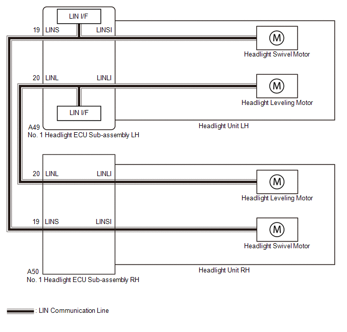
The No. 1 headlight ECU sub-assembly LH sends automatic headlight beam level control signals to each headlight swivel motor and headlight leveling motor via LIN communication.
Each No. 1 headlight ECU sub-assembly and headlight swivel motor and headlight leveling motor communicate via LIN communication.
The headlight swivel motor and headlight leveling motor operates according to power supplied and automatic headlight beam level control signals from its respective No. 1 headlight ECU sub-assembly and sends its operating state to the No. 1 headlight ECU sub-assembly.
The No. 1 headlight ECU sub-assembly LH stores a DTC if it detects that a headlight swivel motor and headlight leveling motor is malfunctioning.
| DTC No. | Detection Item | DTC Detection Condition | Trouble Area | DTC Output from |
|---|---|---|---|---|
| B2412 | Headlight Swivel Motor LH |
| Headlight unit LH | AFS |
| B2413 | Headlight Swivel Motor RH |
| Headlight unit RH | AFS |
| B2417 | Headlight Beam Level Control Motor LH |
| Headlight unit LH | AFS |
| B2418 | Headlight Beam Level Control Motor RH |
| Headlight unit RH | AFS |
WIRING DIAGRAM
CAUTION / NOTICE / HINT
NOTICE:
-
If the No. 1 headlight ECU sub-assembly LH has been replaced, it is necessary to synchronize the vehicle information and initialize the No. 1 headlight ECU sub-assembly LH.
Click here
.gif)
-
If the headlight assembly LH has been replaced, it is necessary to synchronize the vehicle information and initialize the No. 1 headlight ECU sub-assembly LH.*
Click here
- When replacing the No. 1 headlight ECU sub-assembly LH, always replace it with a new one. If a No. 1 headlight ECU sub-assembly LH which was installed to another vehicle is used, the information stored in it will not match the information from the vehicle and a DTC may be stored.
-
When replacing the headlight assembly LH, always replace it with a new one. If a headlight assembly LH which was installed to another vehicle is used, the information stored in it will not match the information from the vehicle and a DTC may be stored.*
- *: for TMMC Made
PROCEDURE
| 1. | CONFIRM MODEL |
(a) Choose the model to be inspected.
| Result | Proceed to |
|---|---|
| for TMC Made | A |
| for TMMC Made | B |
| B | .gif) | GO TO STEP 4 |
|
.gif)
| 2. | CLEAR DTC |
(a) Connect the Techstream to the DLC3.
(b) Turn the engine switch on (IG).
(c) Turn the Techstream on.
(d) Enter the following menus: Body Electrical / AFS / Trouble Codes.
(e) Clear the DTCs.
Body Electrical > AFS > Clear DTCs
|
| 3. | CHECK FOR DTC |
(a) Connect the Techstream to the DLC3.
(b) Turn the engine switch on (IG).
(c) Turn the Techstream on.
(d) Enter the following menus: Body Electrical / AFS / Trouble Codes.
(e) Check for DTCs.
Body Electrical > AFS > Trouble CodesOK:
DTC B2412, B2413, B2417 and B2418 are not output.
| Result | Proceed to |
|---|---|
| OK | A |
| NG (DTC B2412 or B2417 is output) | B |
| NG (DTC B2413 or B2418 is output) | C |
| A | | USE SIMULATION METHOD TO CHECK |
| B | | REPLACE HEADLIGHT UNIT LH |
| C | | REPLACE HEADLIGHT UNIT RH |
| 4. | CLEAR DTC |
(a) Connect the Techstream to the DLC3.
(b) Turn the engine switch on (IG).
(c) Turn the Techstream on.
(d) Enter the following menus: Body Electrical / AFS / Trouble Codes.
(e) Clear the DTCs.
Body Electrical > AFS > Clear DTCs
|
| 5. | CHECK FOR DTC |
(a) Connect the Techstream to the DLC3.
(b) Turn the engine switch on (IG).
(c) Turn the Techstream on.
(d) Enter the following menus: Body Electrical / AFS / Trouble Codes.
(e) Check for DTCs.
Body Electrical > AFS > Trouble CodesOK:
DTC B2412, B2413, B2417 and B2418 are not output.
| Result | Proceed to |
|---|---|
| OK | A |
| NG (DTC B2412 or B2417 is output) | B |
| NG (DTC B2413 or B2418 is output) | C |
| A | | USE SIMULATION METHOD TO CHECK |
| B | | REPLACE HEADLIGHT ASSEMBLY LH |
| C | | REPLACE HEADLIGHT ASSEMBLY RH |
 Headlight Swivel ECU LH Communication (B2410,B2411)
DESCRIPTION Each No. 1 headlight ECU sub-assembly and headlight swivel motor communicate via LIN communication. The headlight swivel motor operates according to power supplied and automatic headlight ...
 Steering Position Sensor (B2414)
DESCRIPTION The No. 1 headlight ECU sub-assembly LH receives steering angle signals from the steering sensor via CAN communication and performs light control. DTC No. Detection Item DTC Detecti ...
Other materials:
Lexus RX (RX 350L, RX450h) 2016-2026 Repair Manual > Air Conditioning System: Parts Location
PARTS LOCATION ILLUSTRATION *A w/o Rear Air Conditioning System *B w/ PTC Heater *C w/ Smog Ventilation Sensor *D w/ Pre-collision System *1 AIR CONDITIONER PRESSURE SENSOR *2 COOLER (AMBIENT TEMP. SENSOR) THERMISTOR *3 COOLER COMPRESSOR ASSEMBLY *4 SEMICONDUC ...
Lexus RX (RX 350L, RX450h) 2016-2026 Repair Manual > Ignition Coil And Spark Plug: Removal
REMOVAL CAUTION / NOTICE / HINT The necessary procedures (adjustment, calibration, initialization or registration) that must be performed after parts are removed and installed, or replaced during ignition coil assembly or spark plug removal/installation are shown below. Necessary Procedure After Par ...
Lexus RX (RX 350L, RX450h) 2016-{YEAR} Owners Manual
- For your information
- Pictorial index
- For safety and security
- Instrument cluster
- Operation of each component
- Driving
- Lexus Display Audio system
- Interior features
- Maintenance and care
- When trouble arises
- Vehicle specifications
- For owners
Lexus RX (RX 350L, RX450h) 2016-{YEAR} Repair Manual

0.0133