Lexus RX (RX 350L, RX450h) 2016-2026 Repair Manual: Left Low Beam Fan Malfunction (B243D,B243E)
DESCRIPTION
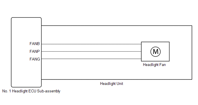
The No. 1 headlight ECU sub-assembly operates the low beam fan to cool the headlight LED unit in order to prevent the headlight LED unit from overheating.
Illuminates the low beam headlights and continuously operates the low beam fan.
The No. 1 headlight ECU sub-assembly monitors the pulse signals from the FANP terminal when the low beam fans are operating.
HINT:
If B243D or B243E is output, the No. 1 headlight ECU sub-assembly performs low beam headlight dimming control.
| DTC No. | Detection Item | DTC Detection Condition | Trouble Area | DTC Output from |
|---|---|---|---|---|
| B243D | Left Low Beam Fan Malfunction |
|
| AFS |
| B243E | Right Low Beam Fan Malfunction |
|
| AFS |
WIRING DIAGRAM
CAUTION / NOTICE / HINT
NOTICE:
-
If the No. 1 headlight ECU sub-assembly LH has been replaced, it is necessary to synchronize the vehicle information and initialize the No. 1 headlight ECU sub-assembly LH.
Click here
.gif)
-
If the headlight assembly LH has been replaced, it is necessary to synchronize the vehicle information and initialize the No. 1 headlight ECU sub-assembly LH.*
Click here
- When replacing the No. 1 headlight ECU sub-assembly LH, always replace it with a new one. If a No. 1 headlight ECU sub-assembly LH which was installed to another vehicle is used, the information stored in it will not match the information from the vehicle and a DTC may be stored.
-
When replacing the headlight assembly LH, always replace it with a new one. If a headlight assembly LH which was installed to another vehicle is used, the information stored in it will not match the information from the vehicle and a DTC may be stored.*
- *: for TMMC Made
PROCEDURE
| 1. | CLEAR DTC |
(a) Connect the Techstream to the DLC3.
(b) Turn the engine switch on (IG).
(c) Turn the Techstream on.
(d) Enter the following menus: Body Electrical / AFS / Trouble Codes.
(e) Clear the DTCs.
Body Electrical > AFS > Clear DTCs
|
.gif)
| 2. | CHECK FOR DTC |
(a) Connect the Techstream to the DLC3.
(b) Turn the engine switch on (IG).
(c) Operate the light control switch to turn on the low beam headlights and wait 120 seconds or more.
(d) Turn the Techstream on.
(e) Enter the following menus: Body Electrical / AFS / Trouble Codes.
(f) Check for DTCs.
Body Electrical > AFS > Trouble CodesOK:
DTC B243D and B243E are not output.
| Result | Proceed to |
|---|---|
| OK | A |
| NG (DTC B243D is output) | B |
| NG (DTC B243E is output) | C |
| A | .gif) | USE SIMULATION METHOD TO CHECK |
| C | | GO TO STEP 6 |
|
| 3. | CHECK HEADLIGHT UNIT LH |
(a) Interchange the headlight unit LH with RH and connect the connectors.
Click here
|
| 4. | CLEAR DTC |
(a) Connect the Techstream to the DLC3.
(b) Turn the engine switch on (IG).
(c) Turn the Techstream on.
(d) Enter the following menus: Body Electrical / AFS / Trouble Codes.
(e) Clear the DTCs.
Body Electrical > AFS > Clear DTCs
|
| 5. | CHECK FOR DTC |
(a) Connect the Techstream to the DLC3.
(b) Turn the engine switch on (IG).
(c) Operate the light control switch to turn on the low beam headlights and wait 120 seconds or more.
(d) Turn the Techstream on.
(e) Enter the following menus: Body Electrical / AFS / Trouble Codes.
(f) Check for DTCs.
Body Electrical > AFS > Trouble Codes| Result | Proceed to |
|---|---|
| DTC B243D is output | A |
| DTC B243E is output (for TMC Made) | B |
| DTC B243E is output (for TMMC Made) | C |
| A | | REPLACE NO. 1 HEADLIGHT ECU SUB-ASSEMBLY LH |
| B | | REPLACE HEADLIGHT UNIT LH |
| C | | REPLACE HEADLIGHT ASSEMBLY LH |
| 6. | CHECK HEADLIGHT UNIT RH |
(a) Interchange the headlight unit RH with LH and connect the connectors.
Click here
|
| 7. | CLEAR DTC |
(a) Connect the Techstream to the DLC3.
(b) Turn the engine switch on (IG).
(c) Turn the Techstream on.
(d) Enter the following menus: Body Electrical / AFS / Trouble Codes.
(e) Clear the DTCs.
Body Electrical > AFS > Clear DTCs
|
| 8. | CHECK FOR DTC |
(a) Connect the Techstream to the DLC3.
(b) Turn the engine switch on (IG).
(c) Operate the light control switch to turn on the low beam headlights and wait 120 seconds or more.
(d) Turn the Techstream on.
(e) Enter the following menus: Body Electrical / AFS / Trouble Codes.
(f) Check for DTCs.
Body Electrical > AFS > Trouble Codes| Result | Proceed to |
|---|---|
| DTC B243E is output | A |
| DTC B243D is output (for TMC Made) | B |
| DTC B243D is output (for TMMC Made) | C |
| A | | REPLACE NO. 1 HEADLIGHT ECU SUB-ASSEMBLY RH |
| B | | REPLACE HEADLIGHT UNIT RH |
| C | | REPLACE HEADLIGHT ASSEMBLY RH |
 Open in IG Circuit (B242E)
DESCRIPTION The No. 1 headlight ECU sub-assembly operates using the power source voltage input from the IG terminal and ECUB terminal. The IG terminal power source voltage is supplied by turning the I ...
 Headlight LH Circuit (B2439,B243A)
DESCRIPTION The No. 1 headlight ECU sub-assembly LH and No. 1 headlight ECU sub-assembly RH internally boost the power supply voltage to ensure a constant supplied current for the lo/hi beam LED of th ...
Other materials:
Lexus RX (RX 350L, RX450h) 2016-2026 Repair Manual > Air Conditioning System: Air Conditioning Compressor Magnetic Clutch Circuit
DESCRIPTION When the air conditioning amplifier assembly is turned on, a magnetic clutch on signal is sent from the MGC terminal of the air conditioning amplifier assembly. Then, the semiconductor pwr integration ECU turns on to operate the magnetic clutch assembly. WIRING DIAGRAM CAUTION / NOTICE ...
Lexus RX (RX 350L, RX450h) 2016-2026 Repair Manual > Smart Access System With Push-button Start (for Entry Function): Dtc Check / Clear
DTC CHECK / CLEAR CHECK FOR DTC NOTICE: When using the Techstream with the engine switch off, connect the Techstream to the DLC3 and turn a courtesy light switch on and off at intervals of 1.5 seconds or less until communication between the Techstream and the vehicle begins. Then select the vehicle ...
Lexus RX (RX 350L, RX450h) 2016-{YEAR} Owners Manual
- For your information
- Pictorial index
- For safety and security
- Instrument cluster
- Operation of each component
- Driving
- Lexus Display Audio system
- Interior features
- Maintenance and care
- When trouble arises
- Vehicle specifications
- For owners
Lexus RX (RX 350L, RX450h) 2016-{YEAR} Repair Manual

0.0104