Lexus RX (RX 350L, RX450h) 2016-2026 Repair Manual: Speaker Circuit
DESCRIPTION
If there is a short in a speaker circuit, the stereo component amplifier assembly detects it and stops output to the speakers.
Thus sound cannot be heard from the speakers even if there is no malfunction in the stereo component amplifier assembly or speakers.
WIRING DIAGRAM
for 9 Speakers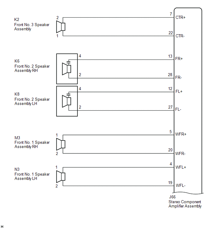 for 9 Speakers
 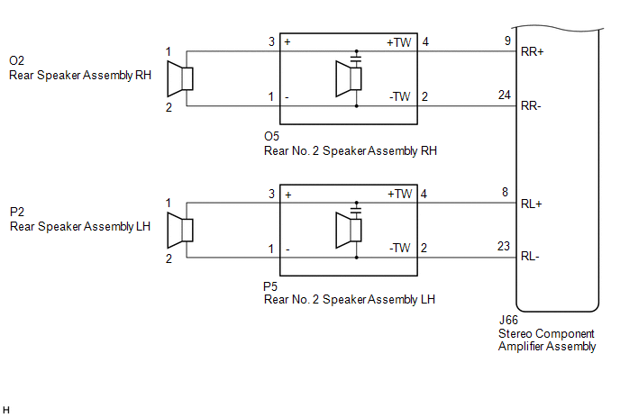 for 12 Speakers
 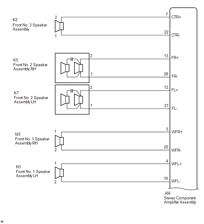 for 12 Speakers
 .png) for 15 Speakers
for 15 Speakers 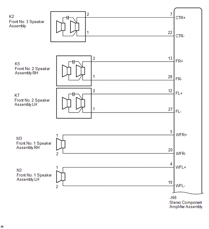 for 15 Speakers
 .png)
CAUTION / NOTICE / HINT
NOTICE:
Depending on the parts that are replaced during vehicle inspection or maintenance, performing initialization, registration or calibration may be needed. Refer to Precaution for Audio and Visual System.
Click here .gif)
PROCEDURE
| 1. | CHECK MODEL |
(a) Choose the model to be inspected.
| Result | Proceed to |
|---|---|
| for 9 Speakers | A |
| for 12 Speakers | B |
| for 15 Speakers | C |
| B | .gif) | GO TO STEP 13 |
| C | | GO TO STEP 26 |
|
.gif)
| 2. | CHECK SPEAKER (OPERATION CHECK) |
| (a) Enter the "System Check Mode" screen. Refer to Check SP Check On in Operation Check. Click here |
|
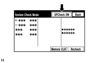
(b) Perform the operation check above and determine the speaker that is not operating.
| Not Operating Speaker | Proceed to |
|---|---|
| Front No. 3 speaker assembly | A |
| Front No. 2 speaker assembly | B |
| Front No. 1 speaker assembly | C |
| Rear speaker assembly or rear No. 2 speaker assembly | D |
HINT:
If sound cannot be heard from any speaker, inspect all of them.
| B | | GO TO STEP 5 |
| C | | GO TO STEP 7 |
| D | | GO TO STEP 9 |
|
| 3. | CHECK HARNESS AND CONNECTOR (STEREO COMPONENT AMPLIFIER ASSEMBLY - FRONT NO. 3 SPEAKER ASSEMBLY) |
(a) Disconnect the J66 stereo component amplifier assembly connector.
(b) Disconnect the K2 front No. 3 speaker assembly connector.
(c) Measure the resistance according to the value(s) in the table below.
Standard Resistance:
| Tester Connection | Condition | Specified Condition |
|---|---|---|
| J66-7 (CTR+) - K2-2 | Always | Below 1 Ω |
| J66-22 (CTR-) - K2-1 | Always | Below 1 Ω |
| J66-7 (CTR+) or K2-2 - Body ground | Always | 10 kΩ or higher |
| J66-22 (CTR-) or K2-1 - Body ground | Always | 10 kΩ or higher |
| NG | | REPAIR OR REPLACE HARNESS OR CONNECTOR |
|
| 4. | INSPECT FRONT NO. 3 SPEAKER ASSEMBLY |
(a) Remove the front No. 3 speaker assembly.
Click here
(b) Inspect the front No. 3 speaker assembly.
Click here
| OK | | PROCEED TO NEXT SUSPECTED AREA SHOWN IN PROBLEM SYMPTOMS TABLE |
| NG | | REPLACE FRONT NO. 3 SPEAKER ASSEMBLY |
| 5. | CHECK HARNESS AND CONNECTOR (STEREO COMPONENT AMPLIFIER ASSEMBLY - FRONT NO. 2 SPEAKER ASSEMBLY) |
(a) Disconnect the J66 stereo component amplifier assembly connector.
(b) Disconnect the K6 and K8 front No. 2 speaker assembly connectors.
(c) Measure the resistance according to the value(s) in the table below.
Standard Resistance:
| Tester Connection | Condition | Specified Condition |
|---|---|---|
| J66-13 (FR+) - K6-4 | Always | Below 1 Ω |
| J66-28 (FR-) - K6-2 | Always | Below 1 Ω |
| J66-12 (FL+) - K8-4 | Always | Below 1 Ω |
| J66-27 (FL-) - K8-2 | Always | Below 1 Ω |
| J66-13 (FR+) or K6-4 - Body ground | Always | 10 kΩ or higher |
| J66-28 (FR-) or K6-2 - Body ground | Always | 10 kΩ or higher |
| J66-12 (FL+) or K8-4 - Body ground | Always | 10 kΩ or higher |
| J66-27 (FL-) or K8-2 - Body ground | Always | 10 kΩ or higher |
| NG | | REPAIR OR REPLACE HARNESS OR CONNECTOR |
|
| 6. | INSPECT FRONT NO. 2 SPEAKER ASSEMBLY |
(a) Remove the front No. 2 speaker assembly.
Click here
(b) Inspect the front No. 2 speaker assembly.
Click here
OK:
Malfunction disappears.
| OK | | END |
| NG | | PROCEED TO NEXT SUSPECTED AREA SHOWN IN PROBLEM SYMPTOMS TABLE |
| 7. | CHECK HARNESS AND CONNECTOR (STEREO COMPONENT AMPLIFIER ASSEMBLY - FRONT NO. 1 SPEAKER ASSEMBLY) |
(a) Disconnect the J66 stereo component amplifier assembly connector.
(b) Disconnect the M3 and N3 front No. 1 speaker assembly connectors.
(c) Measure the resistance according to the value(s) in the table below.
Standard Resistance:
| Tester Connection | Condition | Specified Condition |
|---|---|---|
| J66-5 (WFR+) - M3-1 | Always | Below 1 Ω |
| J66-20 (WFR-) - M3-2 | Always | Below 1 Ω |
| J66-4 (WFL+) - N3-1 | Always | Below 1 Ω |
| J66-19 (WFL-) - N3-2 | Always | Below 1 Ω |
| J66-5 (WFR+) or M3-1 - Body ground | Always | 10 kΩ or higher |
| J66-20 (WFR-) or M3-2 - Body ground | Always | 10 kΩ or higher |
| J66-4 (WFL+) or N3-1 - Body ground | Always | 10 kΩ or higher |
| J66-19 (WFL-) or N3-2 - Body ground | Always | 10 kΩ or higher |
| NG | | REPAIR OR REPLACE HARNESS OR CONNECTOR |
|
| 8. | INSPECT FRONT NO. 1 SPEAKER ASSEMBLY |
(a) Remove the front No. 1 speaker assembly.
Click here
(b) Inspect the front No. 1 speaker assembly.
Click here
| OK | | PROCEED TO NEXT SUSPECTED AREA SHOWN IN PROBLEM SYMPTOMS TABLE |
| NG | | REPLACE FRONT NO. 1 SPEAKER ASSEMBLY |
| 9. | CHECK HARNESS AND CONNECTOR (STEREO COMPONENT AMPLIFIER ASSEMBLY - REAR NO. 2 SPEAKER ASSEMBLY) |
(a) Disconnect the J66 stereo component amplifier assembly connector.
(b) Disconnect the O5 and P5 rear No. 2 speaker assembly connectors.
(c) Measure the resistance according to the value(s) in the table below.
Standard Resistance:
| Tester Connection | Condition | Specified Condition |
|---|---|---|
| J66-9 (RR+) - O5-4 (+TW) | Always | Below 1 Ω |
| J66-24 (RR-) - O5-2 (-TW) | Always | Below 1 Ω |
| J66-8 (RL+) - P5-4 (+TW) | Always | Below 1 Ω |
| J66-23 (RL-) - P5-2 (-TW) | Always | Below 1 Ω |
| J66-9 (RR+) or O5-4 (+TW) - Body ground | Always | 10 kΩ or higher |
| J66-24 (RR-) or O5-2 (-TW) - Body ground | Always | 10 kΩ or higher |
| J66-8 (RL+) or P5-4 (+TW) - Body ground | Always | 10 kΩ or higher |
| J66-23 (RL-) or P5-2 (-TW) - Body ground | Always | 10 kΩ or higher |
| NG | | REPAIR OR REPLACE HARNESS OR CONNECTOR |
|
| 10. | CHECK HARNESS AND CONNECTOR (REAR SPEAKER ASSEMBLY - REAR NO. 2 SPEAKER ASSEMBLY) |
(a) Disconnect the O2 and P2 rear speaker assembly connectors.
(b) Disconnect the O5 and P5 rear No. 2 speaker assembly connectors.
(c) Measure the resistance according to the value(s) in the table below.
Standard Resistance:
| Tester Connection | Condition | Specified Condition |
|---|---|---|
| O2-1 - O5-3 (+) | Always | Below 1 Ω |
| O2-2 - O5-1 (-) | Always | Below 1 Ω |
| P2-1 - P5-3 (+) | Always | Below 1 Ω |
| P2-2 - P5-1 (-) | Always | Below 1 Ω |
| O2-1 or O5-3 (+) - Body ground | Always | 10 kΩ or higher |
| O2-2 or O5-1 (-) - Body ground | Always | 10 kΩ or higher |
| P2-1 or P5-3 (+) - Body ground | Always | 10 kΩ or higher |
| P2-2 or P5-1 (-) - Body ground | Always | 10 kΩ or higher |
| NG | | REPAIR OR REPLACE HARNESS OR CONNECTOR |
|
| 11. | INSPECT REAR SPEAKER ASSEMBLY |
(a) Remove the rear speaker assembly.
Click here
(b) Inspect the rear speaker assembly.
Click here
| NG | | REPLACE REAR SPEAKER ASSEMBLY |
|
| 12. | INSPECT REAR NO.2 SPEAKER ASSEMBLY |
(a) Remove the rear No. 2 speaker assembly.
Click here
(b) Inspect the rear No. 2 speaker assembly.
Click here
OK:
Malfunction disappears.
| OK | | END |
| NG | | PROCEED TO NEXT SUSPECTED AREA SHOWN IN PROBLEM SYMPTOMS TABLE |
| 13. | CHECK SPEAKER (OPERATION CHECK) |
| (a) Enter the "System Check Mode" screen. Refer to Check SP Check On in Operation Check. Click here |
|
(b) Perform the operation check above and determine the speaker that is not operating.
| Not Operating Speaker | Proceed to |
|---|---|
| Front No. 3 speaker assembly | A |
| Front No. 2 speaker assembly | B |
| Front No. 1 speaker assembly | C |
| Rear speaker assembly or rear No. 2 speaker assembly | D |
| Rear No. 3 speaker assembly | E |
HINT:
If sound cannot be heard from any speaker, inspect all of them.
| B | | GO TO STEP 16 |
| C | | GO TO STEP 18 |
| D | | GO TO STEP 20 |
| E | | GO TO STEP 24 |
|
| 14. | CHECK HARNESS AND CONNECTOR (STEREO COMPONENT AMPLIFIER ASSEMBLY - FRONT NO. 3 SPEAKER ASSEMBLY) |
(a) Disconnect the J66 stereo component amplifier assembly connector.
(b) Disconnect the K2 front No. 3 speaker assembly connector.
(c) Measure the resistance according to the value(s) in the table below.
Standard Resistance:
| Tester Connection | Condition | Specified Condition |
|---|---|---|
| J66-7 (CTR+) - K2-2 | Always | Below 1 Ω |
| J66-22 (CTR-) - K2-1 | Always | Below 1 Ω |
| J66-7 (CTR+) or K2-2 - Body ground | Always | 10 kΩ or higher |
| J66-22 (CTR-) or K2-1 - Body ground | Always | 10 kΩ or higher |
| NG | | REPAIR OR REPLACE HARNESS OR CONNECTOR |
|
| 15. | INSPECT FRONT NO. 3 SPEAKER ASSEMBLY |
(a) Remove the front No. 3 speaker assembly.
Click here
(b) Inspect the front No. 3 speaker assembly.
Click here
| OK | | PROCEED TO NEXT SUSPECTED AREA SHOWN IN PROBLEM SYMPTOMS TABLE |
| NG | | REPLACE FRONT NO. 3 SPEAKER ASSEMBLY |
| 16. | CHECK HARNESS AND CONNECTOR (STEREO COMPONENT AMPLIFIER ASSEMBLY - FRONT NO. 2 SPEAKER ASSEMBLY) |
(a) Disconnect the J66 stereo component amplifier assembly connector.
(b) Disconnect the K5 and K7 front No. 2 speaker assembly connectors.
(c) Measure the resistance according to the value(s) in the table below.
Standard Resistance:
| Tester Connection | Condition | Specified Condition |
|---|---|---|
| J66-13 (FR+) - K5-2 | Always | Below 1 Ω |
| J66-28 (FR-) - K5-1 | Always | Below 1 Ω |
| J66-12 (FL+) - K7-2 | Always | Below 1 Ω |
| J66-27 (FL-) - K7-1 | Always | Below 1 Ω |
| J66-13 (FR+) or K5-2 - Body ground | Always | 10 kΩ or higher |
| J66-28 (FR-) or K5-1 - Body ground | Always | 10 kΩ or higher |
| J66-12 (FL+) or K7-2 - Body ground | Always | 10 kΩ or higher |
| J66-27 (FL-) or K7-1 - Body ground | Always | 10 kΩ or higher |
| NG | | REPAIR OR REPLACE HARNESS OR CONNECTOR |
|
| 17. | INSPECT FRONT NO. 2 SPEAKER ASSEMBLY |
(a) Remove the front No. 2 speaker assembly.
Click here
(b) Inspect the front No. 2 speaker assembly.
Click here
OK:
Malfunction disappears.
| OK | | END |
| NG | | PROCEED TO NEXT SUSPECTED AREA SHOWN IN PROBLEM SYMPTOMS TABLE |
| 18. | CHECK HARNESS AND CONNECTOR (STEREO COMPONENT AMPLIFIER ASSEMBLY - FRONT NO. 1 SPEAKER ASSEMBLY) |
(a) Disconnect the J66 stereo component amplifier assembly connector.
(b) Disconnect the M3 and N3 front No. 1 speaker assembly connectors.
(c) Measure the resistance according to the value(s) in the table below.
Standard Resistance:
| Tester Connection | Condition | Specified Condition |
|---|---|---|
| J66-5 (WFR+) - M3-1 | Always | Below 1 Ω |
| J66-20 (WFR-) - M3-2 | Always | Below 1 Ω |
| J66-4 (WFL+) - N3-1 | Always | Below 1 Ω |
| J66-19 (WFL-) - N3-2 | Always | Below 1 Ω |
| J66-5 (WFR+) or M3-1 - Body ground | Always | 10 kΩ or higher |
| J66-20 (WFR-) or M3-2 - Body ground | Always | 10 kΩ or higher |
| J66-4 (WFL+) or N3-1 - Body ground | Always | 10 kΩ or higher |
| J66-19 (WFL-) or N3-2 - Body ground | Always | 10 kΩ or higher |
| NG | | REPAIR OR REPLACE HARNESS OR CONNECTOR |
|
| 19. | INSPECT FRONT NO. 1 SPEAKER ASSEMBLY |
(a) Remove the front No. 1 speaker assembly.
Click here
(b) Inspect the front No. 1 speaker assembly.
Click here
| OK | | PROCEED TO NEXT SUSPECTED AREA SHOWN IN PROBLEM SYMPTOMS TABLE |
| NG | | REPLACE FRONT NO. 1 SPEAKER ASSEMBLY |
| 20. | CHECK HARNESS AND CONNECTOR (STEREO COMPONENT AMPLIFIER ASSEMBLY - REAR NO. 2 SPEAKER ASSEMBLY) |
(a) Disconnect the J66 stereo component amplifier assembly connector.
(b) Disconnect the O5 and P5 rear No. 2 speaker assembly connectors.
(c) Measure the resistance according to the value(s) in the table below.
Standard Resistance:
| Tester Connection | Condition | Specified Condition |
|---|---|---|
| J66-9 (RR+) - O5-4 (+TW) | Always | Below 1 Ω |
| J66-24 (RR-) - O5-2 (-TW) | Always | Below 1 Ω |
| J66-8 (RL+) - P5-4 (+TW) | Always | Below 1 Ω |
| J66-23 (RL-) - P5-2 (-TW) | Always | Below 1 Ω |
| J66-9 (RR+) or O5-4 (+TW) - Body ground | Always | 10 kΩ or higher |
| J66-24 (RR-) or O5-2 (-TW) - Body ground | Always | 10 kΩ or higher |
| J66-8 (RL+) or P5-4 (+TW) - Body ground | Always | 10 kΩ or higher |
| J66-23 (RL-) or P5-2 (-TW) - Body ground | Always | 10 kΩ or higher |
| NG | | REPAIR OR REPLACE HARNESS OR CONNECTOR |
|
| 21. | CHECK HARNESS AND CONNECTOR (REAR SPEAKER ASSEMBLY - REAR NO. 2 SPEAKER ASSEMBLY) |
(a) Disconnect the O2 and P2 rear speaker assembly connectors.
(b) Disconnect the O5 and P5 rear No. 2 speaker assembly connectors.
(c) Measure the resistance according to the value(s) in the table below.
Standard Resistance:
| Tester Connection | Condition | Specified Condition |
|---|---|---|
| O2-1 - O5-3 (+) | Always | Below 1 Ω |
| O2-2 - O5-1 (-) | Always | Below 1 Ω |
| P2-1 - P5-3 (+) | Always | Below 1 Ω |
| P2-2 - P5-1 (-) | Always | Below 1 Ω |
| O2-1 or O5-3 (+) - Body ground | Always | 10 kΩ or higher |
| O2-2 or O5-1 (-) - Body ground | Always | 10 kΩ or higher |
| P2-1 or P5-3 (+) - Body ground | Always | 10 kΩ or higher |
| P2-2 or P5-1 (-) - Body ground | Always | 10 kΩ or higher |
| NG | | REPAIR OR REPLACE HARNESS OR CONNECTOR |
|
| 22. | INSPECT REAR SPEAKER ASSEMBLY |
(a) Remove the rear speaker assembly.
Click here
(b) Inspect the rear speaker assembly.
Click here
| NG | | REPLACE REAR SPEAKER ASSEMBLY |
|
| 23. | INSPECT REAR NO. 2 SPEAKER ASSEMBLY |
(a) Remove the rear No. 2 speaker assembly.
Click here
(b) Inspect the rear No. 2 speaker assembly.
Click here
OK:
Malfunction disappears.
| OK | | END |
| NG | | PROCEED TO NEXT SUSPECTED AREA SHOWN IN PROBLEM SYMPTOMS TABLE |
| 24. | CHECK HARNESS AND CONNECTOR (STEREO COMPONENT AMPLIFIER ASSEMBLY - REAR NO. 3 SPEAKER ASSEMBLY) |
(a) Disconnect the J66 stereo component amplifier assembly connector.
(b) Disconnect the S53 rear No. 3 speaker assembly connector.
(c) Measure the resistance according to the value(s) in the table below.
Standard Resistance:
| Tester Connection | Condition | Specified Condition |
|---|---|---|
| J66-6 (WF1+) - S53-1 | Always | Below 1 Ω |
| J66-21 (WF1-) - S53-2 | Always | Below 1 Ω |
| J66-6 (WF1+) or S53-1 - Body ground | Always | 10 kΩ or higher |
| J66-21 (WF1-) or S53-2 - Body ground | Always | 10 kΩ or higher |
| NG | | REPAIR OR REPLACE HARNESS OR CONNECTOR |
|
| 25. | INSPECT REAR NO. 3 SPEAKER ASSEMBLY |
(a) Remove the rear No. 3 speaker assembly.
w/o Rear No. 2 Seat: Click here
w/ Rear No. 2 Seat: Click here
(b) Inspect the rear No. 3 speaker assembly.
w/o Rear No. 2 Seat: Click here
w/ Rear No. 2 Seat: Click here
| OK | | PROCEED TO NEXT SUSPECTED AREA SHOWN IN PROBLEM SYMPTOMS TABLE |
| NG | | REPLACE REAR NO. 3 SPEAKER ASSEMBLY |
| 26. | CHECK SPEAKER (OPERATION CHECK) |
| (a) Enter the "System Check Mode" screen. Refer to Check SP Check On in Operation Check. Click here |
|
(b) Perform the operation check above and determine the speaker that is not operating.
| Not Operating Speaker | Proceed to |
|---|---|
| Front No. 3 speaker assembly | A |
| Front No. 2 speaker assembly | B |
| Front No. 1 speaker assembly | C |
| Rear speaker assembly or rear No. 2 speaker assembly | D |
| Rear No. 3 speaker assembly | E |
| Quarter side speaker assembly | F |
HINT:
If sound cannot be heard from any speaker, inspect all of them.
| B | | GO TO STEP 29 |
| C | | GO TO STEP 31 |
| D | | GO TO STEP 33 |
| E | | GO TO STEP 37 |
| F | | GO TO STEP 39 |
|
| 27. | CHECK HARNESS AND CONNECTOR (STEREO COMPONENT AMPLIFIER ASSEMBLY - FRONT NO. 3 SPEAKER ASSEMBLY) |
(a) Disconnect the J66 stereo component amplifier assembly connector.
(b) Disconnect the K2 front No. 3 speaker assembly connector.
(c) Measure the resistance according to the value(s) in the table below.
Standard Resistance:
| Tester Connection | Condition | Specified Condition |
|---|---|---|
| J66-7 (CTR+) - K2-2 | Always | Below 1 Ω |
| J66-22 (CTR-) - K2-1 | Always | Below 1 Ω |
| J66-7 (CTR+) or K2-2 - Body ground | Always | 10 kΩ or higher |
| J66-22 (CTR-) or K2-1 - Body ground | Always | 10 kΩ or higher |
| NG | | REPAIR OR REPLACE HARNESS OR CONNECTOR |
|
| 28. | INSPECT FRONT NO. 3 SPEAKER ASSEMBLY |
(a) Remove the front No. 3 speaker assembly.
Click here
(b) Inspect the front No. 3 speaker assembly.
Click here
OK:
Malfunction disappears.
| OK | | END |
| NG | | PROCEED TO NEXT SUSPECTED AREA SHOWN IN PROBLEM SYMPTOMS TABLE |
| 29. | CHECK HARNESS AND CONNECTOR (STEREO COMPONENT AMPLIFIER ASSEMBLY - FRONT NO. 2 SPEAKER ASSEMBLY) |
(a) Disconnect the J66 stereo component amplifier assembly connector.
(b) Disconnect the K5 and K7 front No. 2 speaker assembly connectors.
(c) Measure the resistance according to the value(s) in the table below.
Standard Resistance:
| Tester Connection | Condition | Specified Condition |
|---|---|---|
| J66-13 (FR+) - K5-2 | Always | Below 1 Ω |
| J66-28 (FR-) - K5-1 | Always | Below 1 Ω |
| J66-12 (FL+) - K7-2 | Always | Below 1 Ω |
| J66-27 (FL-) - K7-1 | Always | Below 1 Ω |
| J66-13 (FR+) or K5-2 - Body ground | Always | 10 kΩ or higher |
| J66-28 (FR-) or K5-1 - Body ground | Always | 10 kΩ or higher |
| J66-12 (FL+) or K7-2 - Body ground | Always | 10 kΩ or higher |
| J66-27 (FL-) or K7-1 - Body ground | Always | 10 kΩ or higher |
| NG | | REPAIR OR REPLACE HARNESS OR CONNECTOR |
|
| 30. | INSPECT FRONT NO. 1 SPEAKER ASSEMBLY |
(a) Remove the front No. 2 speaker assembly.
Click here
(b) Inspect the front No. 2 speaker assembly.
Click here
(c) Check that the malfunction disappears when a new or known good front No. 2 speaker assembly is installed.
Click here
OK:
Malfunction disappears.
| OK | | END |
| NG | | PROCEED TO NEXT SUSPECTED AREA SHOWN IN PROBLEM SYMPTOMS TABLE |
| 31. | CHECK HARNESS AND CONNECTOR (STEREO COMPONENT AMPLIFIER ASSEMBLY - FRONT NO. 1 SPEAKER ASSEMBLY) |
(a) Disconnect the J66 stereo component amplifier assembly connector.
(b) Disconnect the M3 and N3 front No. 1 speaker assembly connectors.
(c) Measure the resistance according to the value(s) in the table below.
Standard Resistance:
| Tester Connection | Condition | Specified Condition |
|---|---|---|
| J66-5 (WFR+) - M3-1 | Always | Below 1 Ω |
| J66-20 (WFR-) - M3-2 | Always | Below 1 Ω |
| J66-4 (WFL+) - N3-1 | Always | Below 1 Ω |
| J66-19 (WFL-) - N3-2 | Always | Below 1 Ω |
| J66-5 (WFR+) or M3-1 - Body ground | Always | 10 kΩ or higher |
| J66-20 (WFR-) or M3-2 - Body ground | Always | 10 kΩ or higher |
| J66-4 (WFL+) or N3-1 - Body ground | Always | 10 kΩ or higher |
| J66-19 (WFL-) or N3-2 - Body ground | Always | 10 kΩ or higher |
| NG | | REPAIR OR REPLACE HARNESS OR CONNECTOR |
|
| 32. | INSPECT FRONT NO. 1 SPEAKER ASSEMBLY |
(a) Remove the front No. 1 speaker assembly.
Click here
(b) Inspect the front No. 1 speaker assembly.
Click here
| OK | | PROCEED TO NEXT SUSPECTED AREA SHOWN IN PROBLEM SYMPTOMS TABLE |
| NG | | REPLACE FRONT NO. 1 SPEAKER ASSEMBLY |
| 33. | CHECK HARNESS AND CONNECTOR (STEREO COMPONENT AMPLIFIER ASSEMBLY - REAR NO. 2 SPEAKER ASSEMBLY) |
(a) Disconnect the J66 stereo component amplifier assembly connector.
(b) Disconnect the O5 and P5 rear No. 2 speaker assembly connectors.
(c) Measure the resistance according to the value(s) in the table below.
Standard Resistance:
| Tester Connection | Condition | Specified Condition |
|---|---|---|
| J66-9 (RR+) - O5-4 (+TW) | Always | Below 1 Ω |
| J66-24 (RR-) - O5-2 (-TW) | Always | Below 1 Ω |
| J66-8 (RL+) - P5-4 (+TW) | Always | Below 1 Ω |
| J66-23 (RL-) - P5-2 (-TW) | Always | Below 1 Ω |
| J66-9 (RR+) or O5-4 (+TW) - Body ground | Always | 10 kΩ or higher |
| J66-24 (RR-) or O5-2 (-TW) - Body ground | Always | 10 kΩ or higher |
| J66-8 (RL+) or P5-4 (+TW) - Body ground | Always | 10 kΩ or higher |
| J66-23 (RL-) or P5-2 (-TW) - Body ground | Always | 10 kΩ or higher |
| NG | | REPAIR OR REPLACE HARNESS OR CONNECTOR |
|
| 34. | CHECK HARNESS AND CONNECTOR (REAR SPEAKER ASSEMBLY - REAR NO. 2 SPEAKER ASSEMBLY) |
(a) Disconnect the O2 and P2 rear speaker assembly connectors.
(b) Disconnect the O5 and P5 rear No. 2 speaker assembly connectors.
(c) Measure the resistance according to the value(s) in the table below.
Standard Resistance:
| Tester Connection | Condition | Specified Condition |
|---|---|---|
| O2-1 - O5-3 (+) | Always | Below 1 Ω |
| O2-2 - O5-1 (-) | Always | Below 1 Ω |
| P2-1 - P5-3 (+) | Always | Below 1 Ω |
| P2-2 - P5-1 (-) | Always | Below 1 Ω |
| O2-1 or O5-3 (+) - Body ground | Always | 10 kΩ or higher |
| O2-2 or O5-1 (-) - Body ground | Always | 10 kΩ or higher |
| P2-1 or P5-3 (+) - Body ground | Always | 10 kΩ or higher |
| P2-2 or P5-1 (-) - Body ground | Always | 10 kΩ or higher |
| NG | | REPAIR OR REPLACE HARNESS OR CONNECTOR |
|
| 35. | INSPECT REAR SPEAKER ASSEMBLY |
(a) Remove the rear speaker assembly.
Click here
(b) Inspect the rear speaker assembly.
Click here
| NG | | REPLACE REAR SPEAKER ASSEMBLY |
|
| 36. | INSPECT REAR NO. 2 SPEAKER ASSEMBLY |
(a) Remove the rear No. 2 speaker assembly.
Click here
(b) Inspect the rear No. 2 speaker assembly.
Click here
OK:
Malfunction disappears.
| OK | | END |
| NG | | PROCEED TO NEXT SUSPECTED AREA SHOWN IN PROBLEM SYMPTOMS TABLE |
| 37. | CHECK HARNESS AND CONNECTOR (STEREO COMPONENT AMPLIFIER ASSEMBLY - REAR NO. 3 SPEAKER ASSEMBLY) |
(a) Disconnect the J66 stereo component amplifier assembly connector.
(b) Disconnect the S53 rear No. 3 speaker assembly connector.
(c) Measure the resistance according to the value(s) in the table below.
Standard Resistance:
| Tester Connection | Condition | Specified Condition |
|---|---|---|
| J66-6 (WF1+) - S53-1 | Always | Below 1 Ω |
| J66-21 (WF1-) - S53-2 | Always | Below 1 Ω |
| J66-6 (WF1+) or S53-1 - Body ground | Always | 10 kΩ or higher |
| J66-21 (WF1-) or S53-2 - Body ground | Always | 10 kΩ or higher |
| NG | | REPAIR OR REPLACE HARNESS OR CONNECTOR |
|
| 38. | INSPECT REAR NO. 3 SPEAKER ASSEMBLY |
(a) Remove the rear No. 3 speaker assembly.
w/o Rear No. 2 Seat: Click here
w/ Rear No. 2 Seat: Click here
(b) Inspect the rear No. 3 speaker assembly.
w/o Rear No. 2 Seat: Click here
w/ Rear No. 2 Seat: Click here
| OK | | PROCEED TO NEXT SUSPECTED AREA SHOWN IN PROBLEM SYMPTOMS TABLE |
| NG | | REPLACE REAR NO. 3 SPEAKER ASSEMBLY |
| 39. | CHECK HARNESS AND CONNECTOR (STEREO COMPONENT AMPLIFIER ASSEMBLY - QUARTER SIDE SPEAKER ASSEMBLY) |
(a) Disconnect the J66 stereo component amplifier assembly connector.
(b) Disconnect the R25 and S38 quarter side speaker assembly connectors.
(c) Measure the resistance according to the value(s) in the table below.
Standard Resistance:
| Tester Connection | Condition | Specified Condition |
|---|---|---|
| J66-11 (SR+) - R25-2 | Always | Below 1 Ω |
| J66-26 (SR-) - R25-1 | Always | Below 1 Ω |
| J66-10 (SL+) - S38-2 | Always | Below 1 Ω |
| J66-25 (SL-) - S38-1 | Always | Below 1 Ω |
| J66-11 (SR+) or R25-2 - Body ground | Always | 10 kΩ or higher |
| J66-26 (SR-) or R25-1 - Body ground | Always | 10 kΩ or higher |
| J66-10 (SL+) or S38-2 - Body ground | Always | 10 kΩ or higher |
| J66-25 (SL-) or S38-1 - Body ground | Always | 10 kΩ or higher |
| NG | | REPAIR OR REPLACE HARNESS OR CONNECTOR |
|
| 40. | INSPECT QUARTER SIDE SPEAKER ASSEMBLY |
(a) Remove the quarter side speaker assembly.
w/o Rear No. 2 Seat: Click here
w/ Rear No. 2 Seat: Click here
(b) Inspect the quarter side speaker assembly.
w/o Rear No. 2 Seat: Click here
w/ Rear No. 2 Seat: Click here
| OK | | PROCEED TO NEXT SUSPECTED AREA SHOWN IN PROBLEM SYMPTOMS TABLE |
| NG | | REPLACE QUARTER SIDE SPEAKER ASSEMBLY |
 Sound Signal Circuit between Radio Receiver and Stereo Jack Adapter
DESCRIPTION The No. 1 stereo jack adapter assembly sends the sound signal from an external device to the radio receiver assembly via this circuit. The sound signal that has been sent is amplified by t ...
 Data Signal Circuit between Radio Receiver and Stereo Jack Adapter
DESCRIPTION The No. 1 stereo jack adapter assembly sends the sound data signal or image data signal from a USB device to the radio receiver assembly via this circuit. WIRING DIAGRAM PROCEDURE 1. ...
Other materials:
Lexus RX (RX 350L, RX450h) 2016-2026 Repair Manual > Steering Lock System: IG2 Signal Malfunction (B2788)
DESCRIPTION This DTC is stored when the steering lock ECU (steering lock actuator or upper bracket assembly) detects an IG2 power supply malfunction. HINT: The steering lock ECU (steering lock actuator or upper bracket assembly) is not connected to the CAN communication system. However, the steering ...
Lexus RX (RX 350L, RX450h) 2016-2026 Repair Manual > Lighting System (w/ Automatic Headlight Beam Level Control System): Right Headlight ECU Malfunction (B242C,B242D)
DESCRIPTION The No. 1 headlight ECU sub-assembly LH stores a DTC if it detects an internal malfunction. for Multiple Beam Headlight DTC No. Detection Item DTC Detection Condition Trouble Area DTC Output from B242C Right Headlight ECU Malfunction
The engine switch is on (IG).
...
Lexus RX (RX 350L, RX450h) 2016-{YEAR} Owners Manual
- For your information
- Pictorial index
- For safety and security
- Instrument cluster
- Operation of each component
- Driving
- Lexus Display Audio system
- Interior features
- Maintenance and care
- When trouble arises
- Vehicle specifications
- For owners
Lexus RX (RX 350L, RX450h) 2016-{YEAR} Repair Manual

0.0142