Lexus RX (RX 350L, RX450h) 2016-2026 Repair Manual: Headlight Dimmer Switch Circuit
DESCRIPTION
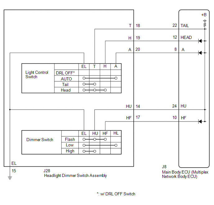
The main body ECU (multiplex network body ECU) receives the following switch information:
- Light control switch in DRL OFF*, tail, head, AUTO position
- Dimmer switch in high, low or high flash (pass) position
- *: w/ DRL OFF Switch
WIRING DIAGRAM
CAUTION / NOTICE / HINT
NOTICE:
Before replacing the main body ECU (multiplex network body ECU), refer to Registration.
Click here .gif)
PROCEDURE
| 1. | READ VALUE USING TECHSTREAM |
(a) Connect the Techstream to the DLC3.
(b) Turn the engine switch on (IG).
(c) Turn the Techstream on.
(d) Enter the following menus: Body Electrical / Main Body / Data List.
(e) Read the Data List according to the display on the Techstream.
Body Electrical > Main Body > Data List| Tester Display | Measurement Item | Range | Normal Condition | Diagnostic Note |
|---|---|---|---|---|
| Dimmer SW | Dimmer switch high position signal | OFF or ON | OFF: Dimmer switch in low position ON: Dimmer switch in high or high flash position | - |
| Passing Light SW | Dimmer switch high flash position (pass) signal | OFF or ON | OFF: Dimmer switch not in high flash position ON: Dimmer switch in high flash position | - |
| Auto Light SW | Light control switch AUTO position signal | OFF or ON | OFF: Light control switch not in AUTO position ON: Light control switch in AUTO position | - |
| Head Light SW (Head) | Light control switch head position signal | OFF or ON | OFF: Light control switch not in head position ON: Light control switch in head position | - |
| Head Light SW (Tail) | Light control switch tail position signal | OFF or ON | OFF: Light control switch not in tail or head position ON: Light control switch in tail or head position | - |
| Tester Display |
|---|
| Dimmer SW |
| Passing Light SW |
| Auto Light SW |
| Head Light SW (Head) |
| Head Light SW (Tail) |
OK:
Normal conditions listed above are displayed.
| OK | .gif) | PROCEED TO NEXT SUSPECTED AREA SHOWN IN PROBLEM SYMPTOMS TABLE |
|
.gif)
| 2. | INSPECT HEADLIGHT DIMMER SWITCH ASSEMBLY |
(a) Remove the headlight dimmer switch assembly.
Click here
(b) Inspect the headlight dimmer switch assembly.
Click here
| NG | | REPLACE HEADLIGHT DIMMER SWITCH ASSEMBLY |
|
| 3. | CHECK HARNESS AND CONNECTOR (HEADLIGHT DIMMER SWITCH ASSEMBLY - MAIN BODY ECU (MULTIPLEX NETWORK BODY ECU) AND BODY GROUND) |
(a) Disconnect the J8 main body ECU (multiplex network body ECU) connector.
(b) Measure the resistance according to the value(s) in the table below.
Standard Resistance:
| Tester Connection | Condition | Specified Condition |
|---|---|---|
| J28-18 (T) - J8-22 (TAIL) | Always | Below 1 Ω |
| J28-19 (H) - J8-12 (HEAD) | Always | Below 1 Ω |
| J28-20 (A) - J8-8 (A) | Always | Below 1 Ω |
| J28-14 (HU) - J8-24 (HU) | Always | Below 1 Ω |
| J28-17 (HF) - J8-10 (HF) | Always | Below 1 Ω |
| J28-18 (T) or J8-22 (TAIL) - Body ground | Always | 10 kΩ or higher |
| J28-19 (H) or J8-12 (HEAD) - Body ground | Always | 10 kΩ or higher |
| J28-20 (A) or J8-8 (A) - Body ground | Always | 10 kΩ or higher |
| J28-14 (HU) or J8-24 (HU) - Body ground | Always | 10 kΩ or higher |
| J28-17 (HF) or J8-10 (HF) - Body ground | Always | 10 kΩ or higher |
| J28-15 (EL) - Body ground | Always | Below 1 Ω |
| OK | | REPLACE MAIN BODY ECU (MULTIPLEX NETWORK BODY ECU) |
| NG | | REPAIR OR REPLACE HARNESS OR CONNECTOR |
 Automatic High Beam System does not Operate or Operation Indicator does not Illuminate
DESCRIPTION The main body ECU (multiplex network body ECU) controls the automatic high beam system based on signals received from the forward recognition camera. WIRING DIAGRAM CAUTION / NOTICE / HIN ...
 Daytime Running Light Relay Circuit
DESCRIPTION The main body ECU (multiplex network body ECU) controls the daytime running lights. WIRING DIAGRAM CAUTION / NOTICE / HINT NOTICE:
Inspect the fuses for circuits related to this system ...
Other materials:
Lexus RX (RX 350L, RX450h) 2016-2026 Owners Manual > For safe use: Before driving
Floor mat
Use only floor mats designed specifically for vehicles of the same model and
model year as your vehicle. Fix them securely in place onto the carpet.
1. Insert the retaining hooks (clips) into
the floor mat eyelets.
2. Turn the upper knob of each retaining
hook (clip) to secure the ...
Lexus RX (RX 350L, RX450h) 2016-2026 Repair Manual > Blind Spot Monitor Sensor: Components
COMPONENTS ILLUSTRATION *1 BLIND SPOT MONITOR SENSOR LH *2 BLIND SPOT MONITOR SENSOR RH N*m (kgf*cm, ft.*lbf): Specified torque - - ...
Lexus RX (RX 350L, RX450h) 2016-{YEAR} Owners Manual
- For your information
- Pictorial index
- For safety and security
- Instrument cluster
- Operation of each component
- Driving
- Lexus Display Audio system
- Interior features
- Maintenance and care
- When trouble arises
- Vehicle specifications
- For owners
Lexus RX (RX 350L, RX450h) 2016-{YEAR} Repair Manual

0.013