Lexus RX (RX 350L, RX450h) 2016-2026 Repair Manual: Daytime Running Light Relay Circuit
DESCRIPTION
The main body ECU (multiplex network body ECU) controls the daytime running lights.
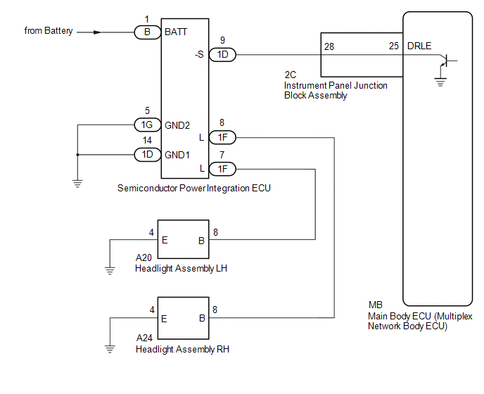
WIRING DIAGRAM
CAUTION / NOTICE / HINT
NOTICE:
- Inspect the fuses for circuits related to this system before performing the following procedure.
-
Before replacing the main body ECU (multiplex network body ECU), refer to Registration.
Click here
.gif)
PROCEDURE
| 1. | PERFORM ACTIVE TEST USING TECHSTREAM |
(a) Connect the Techstream to the DLC3.
(b) Turn the engine switch on (IG).
(c) Turn the Techstream on.
(d) Enter the following menus: Body Electrical / Main Body / Active Test.
(e) Perform the Active Test according to the display on the Techstream.
Body Electrical > Main Body > Active Test| Tester Display | Measurement Item | Control Range | Diagnostic Note |
|---|---|---|---|
| Daytime Running Light | Daytime running lights | OFF/ON | This Active Test can only be performed when the customization item DRL function is set to "ON" using the Techstream. |
| Tester Display |
|---|
| Daytime Running Light |
OK:
Daytime running lights illuminate.
| OK | .gif) | PROCEED TO NEXT SUSPECTED AREA SHOWN IN PROBLEM SYMPTOMS TABLE |
|
.gif)
| 2. | CHECK SEMICONDUCTOR POWER INTEGRATION ECU |
(a) Using a voltmeter, check the signal reading of the semiconductor power integration ECU.
Click here
OK:
Output signal reading is normal.
| NG | | INSPECT SEMICONDUCTOR POWER INTEGRATION ECU (RESULTS OF SIGNAL READING CHECK) |
|
| 3. | CHECK HARNESS AND CONNECTOR (SEMICONDUCTOR POWER INTEGRATION ECU POWER SOURCE AND BODY GROUND) |
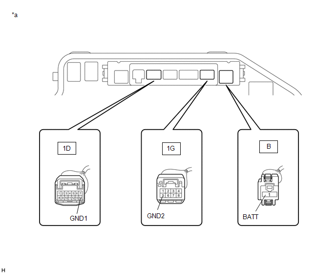
| *a | Component without semiconductor power integration ECU connected (Engine Room Relay Block and Junction Block Assembly) | - | - |
(a) Remove the semiconductor power integration ECU from the engine room relay block and junction block assembly.
Click here
(b) Measure the voltage according to the value(s) in the table below.
Standard Voltage:
| Tester Connection | Condition | Specified Condition |
|---|---|---|
| B-1 (BATT) - Body ground | Always | 11 to 14 V |
(c) Measure the resistance according to the value(s) in the table below.
Standard Resistance:
| Tester Connection | Condition | Specified Condition |
|---|---|---|
| 1D-14 (GND1) - Body ground | Always | Below 1 Ω |
| 1G-5 (GND2) - Body ground | Always | Below 1 Ω |
| NG | | REPAIR OR REPLACE HARNESS OR CONNECTOR |
|
| 4. | CHECK HARNESS AND CONNECTOR (SEMICONDUCTOR POWER INTEGRATION ECU - INSTRUMENT PANEL JUNCTION BLOCK ASSEMBLY) |
(a) Disconnect the 2C instrument panel junction block assembly connector.
(b) Measure the resistance according to the value(s) in the table below.
Standard Resistance:
| Tester Connection | Condition | Specified Condition |
|---|---|---|
| 1D-9 (-S) - 2C-28 | Always | Below 1 Ω |
| 1D-9 (-S) or 2C-28 - Body ground | Always | 10 kΩ or higher |
| NG | | REPAIR OR REPLACE HARNESS OR CONNECTOR |
|
| 5. | INSPECT INSTRUMENT PANEL JUNCTION BLOCK ASSEMBLY |
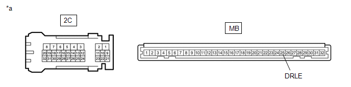
| *a | Component without harness connected (Instrument Panel Junction Block Assembly) | - | - |
(a) Remove the main body ECU (multiplex network body ECU) from the instrument panel junction block assembly.
Click here
(b) Measure the resistance according to the value(s) in the table below.
Standard Resistance:
| Tester Connection | Condition | Specified Condition |
|---|---|---|
| 2C-28 - MB-25 (DRLE) | Always | Below 1 Ω |
| NG | | REPLACE INSTRUMENT PANEL JUNCTION BLOCK ASSEMBLY |
|
| 6. | REPLACE SEMICONDUCTOR POWER INTEGRATION ECU |
(a) Replace the semiconductor power integration ECU with a new one.
Click here
|
| 7. | CHECK OPERATION (DAYTIME RUNNING LIGHTS) |
(a) Check the operation of the daytime running lights.
OK:
Daytime running lights operate normally.
| OK | | END (SEMICONDUCTOR POWER INTEGRATION ECU WAS DEFECTIVE) |
| NG | | REPLACE MAIN BODY ECU (MULTIPLEX NETWORK BODY ECU) |
 Headlight Dimmer Switch Circuit
DESCRIPTION The main body ECU (multiplex network body ECU) receives the following switch information:
Light control switch in DRL OFF*, tail, head, AUTO position
Dimmer switch in high, low or hig ...
 Turn Signal Light Circuit
DESCRIPTION The combination meter assembly controls the illumination and turning off of the rear turn signal lights. WIRING DIAGRAM PROCEDURE 1. CHECK OPERATION (REAR TURN SIGNAL LIGHTS) (a) ...
Other materials:
Lexus RX (RX 350L, RX450h) 2016-2026 Repair Manual > Lighting System (w/ Automatic Headlight Beam Level Control System): Open in IG Circuit (B242E)
DESCRIPTION The No. 1 headlight ECU sub-assembly operates using the power source voltage input from the IG terminal and ECUB terminal. The IG terminal power source voltage is supplied by turning the IG1 relay to ON. The No. 1 headlight ECU sub-assembly receives engine switch on (IG) signals from the ...
Lexus RX (RX 350L, RX450h) 2016-2026 Repair Manual > Front Door Speaker: Inspection
INSPECTION PROCEDURE 1. INSPECT FRONT NO. 1 SPEAKER ASSEMBLY (a) With the speaker installed, check that there is no looseness or other abnormalities. (b) Check that there is no foreign matter in the speaker, no tears on the speaker cone or other abnormalities. (c) Measure the resistance of the sp ...
Lexus RX (RX 350L, RX450h) 2016-{YEAR} Owners Manual
- For your information
- Pictorial index
- For safety and security
- Instrument cluster
- Operation of each component
- Driving
- Lexus Display Audio system
- Interior features
- Maintenance and care
- When trouble arises
- Vehicle specifications
- For owners
Lexus RX (RX 350L, RX450h) 2016-{YEAR} Repair Manual

0.0106