Lexus RX (RX 350L, RX450h) 2016-2026 Repair Manual: Removal
REMOVAL
CAUTION / NOTICE / HINT
The necessary procedures (adjustment, calibration, initialization, or registration) that must be performed after parts are removed, installed, or replaced during brake pedal support assembly removal/installation are shown below.
Necessary Procedure After Parts Removed/Installed/Replaced| Replacement Part or Procedure | Necessary Procedures | Effects/Inoperative when not Performed | Link |
|---|---|---|---|
| Disconnect cable from negative battery terminal | Memorize steering angle neutral point | Lane control system | |
| Pre-collision system | |||
| Intelligent clearance sonar system | |||
| Lighting system (w/ Automatic Headlight Beam Level Control System) | | ||
| Parking assist monitor system | | ||
| Panoramic view monitor system | | ||
| Initialize back door lock | Power door lock control system | | |
| Reset back door close position | Power back door system (w/ Outside Door Control Switch) | |
PROCEDURE
1. REMOVE LOWER NO. 1 INSTRUMENT PANEL AIRBAG ASSEMBLY
Click here .gif)
2. REMOVE STOP LIGHT SWITCH ASSEMBLY
Click here
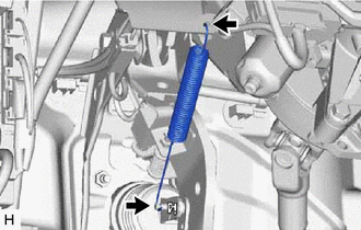
3. REMOVE BRAKE PEDAL RETURN SPRING
| (a) Remove the brake pedal return spring from the instrument panel reinforcement assembly and push rod pin. |
|
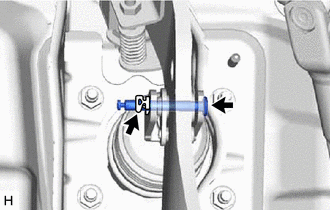
4. REMOVE PUSH ROD PIN
| (a) Remove the clip and push rod pin. |
|
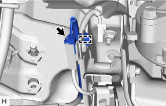
5. REMOVE BRAKE PEDAL SUPPORT ASSEMBLY
| (a) Disconnect the connector and disengage the clamp. |
|
| (b) Remove the 2 bolts and separate the brake pedal support assembly from the instrument panel reinforcement assembly. |
|
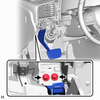
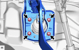
| (c) Remove the 4 nuts and brake pedal support assembly. |
|
 Components
COMPONENTS ILLUSTRATION *1 BRAKE PEDAL RETURN SPRING *2 BRAKE PEDAL SUPPORT ASSEMBLY *3 PUSH ROD PIN *4 STOP LIGHT SWITCH ASSEMBLY *5 BRAKE MASTER CYLINDER PUSH ROD CLEVIS ...
 Disassembly
DISASSEMBLY PROCEDURE 1. REMOVE BRAKE PEDAL SUB-ASSEMBLY (a) Disengage the 2 clamps. (b) Remove the bolt, nut and brake pedal sub-assembly from the brake pedal support sub-assembly. ...
Other materials:
Lexus RX (RX 350L, RX450h) 2016-2026 Repair Manual > Audio And Visual System (for 8 Inch Display): Registered Device cannot be Deleted
PROCEDURE 1. DELETE OPERATION (a) Check if a registered portable player can be deleted normally. OK: Registered portable player can be deleted normally. OK END NG PROCEED TO NEXT SUSPECTED AREA SHOWN IN PROBLEM SYMPTOMS TABLE ...
Lexus RX (RX 350L, RX450h) 2016-2026 Repair Manual > Road Sign Assist System: Problem Symptoms Table
PROBLEM SYMPTOMS TABLE HINT:
Use the table below to help determine the cause of problem symptoms. If multiple suspected areas are listed, the potential causes of the symptoms are listed in order of probability in the "Suspected Area" column of the table. Check each symptom by checking the suspect ...
Lexus RX (RX 350L, RX450h) 2016-{YEAR} Owners Manual
- For your information
- Pictorial index
- For safety and security
- Instrument cluster
- Operation of each component
- Driving
- Lexus Display Audio system
- Interior features
- Maintenance and care
- When trouble arises
- Vehicle specifications
- For owners
Lexus RX (RX 350L, RX450h) 2016-{YEAR} Repair Manual

0.0114