Lexus RX (RX 350L, RX450h) 2016-2026 Repair Manual: Hazard Warning Switch Circuit
DESCRIPTION
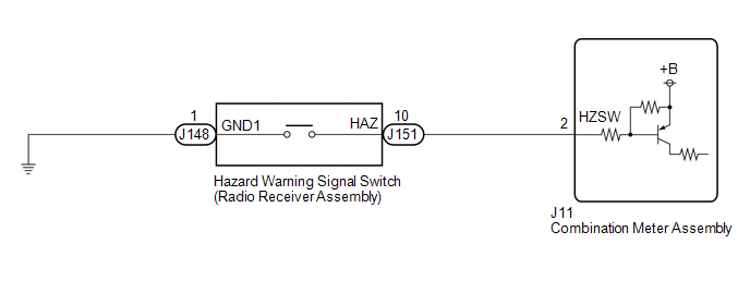
The combination meter assembly receives the hazard warning signal switch on signal and controls the operation of the hazard warning lights.
WIRING DIAGRAM
CAUTION / NOTICE / HINT
NOTICE:
When replacing the combination meter assembly, always replace it with a new one. If a combination meter assembly which was installed to another vehicle is used, the information stored in it will not match the information from the vehicle and a DTC may be stored.
PROCEDURE
| 1. | READ VALUE USING TECHSTREAM |
(a) Connect the Techstream to the DLC3.
(b) Turn the engine switch on (IG).
(c) Turn the Techstream on.
(d) Enter the following menus: Body Electrical / Combination Meter / Data List.
(e) Read the Data List according to the display on the Techstream.
Body Electrical > Combination Meter > Data List| Tester Display | Measurement Item | Range | Normal Condition | Diagnostic Note |
|---|---|---|---|---|
| Hazard Flasher Switch | Hazard warning signal switch signal | OFF or ON | OFF: Hazard warning signal switch off ON: Hazard warning signal switch on | - |
| Tester Display |
|---|
| Hazard Flasher Switch |
OK:
Normal conditions listed above are displayed.
| OK | .gif) | PROCEED TO NEXT SUSPECTED AREA SHOWN IN PROBLEM SYMPTOMS TABLE |
|
.gif)
| 2. | INSPECT HAZARD WARNING SIGNAL SWITCH (RADIO RECEIVER ASSEMBLY) |
(a) Remove the hazard warning signal switch (radio receiver assembly).
Click here .gif)
(b) Inspect the hazard warning signal switch (radio receiver assembly).
Click here
| NG | | REPLACE HAZARD WARNING SIGNAL SWITCH (RADIO RECEIVER ASSEMBLY) |
|
| 3. | CHECK HARNESS AND CONNECTOR (HAZARD WARNING SIGNAL SWITCH - COMBINATION METER ASSEMBLY AND BODY GROUND) |
(a) Disconnect the J11 combination meter assembly connector.
(b) Measure the resistance according to the value(s) in the table below.
Standard Resistance:
| Tester Connection | Condition | Specified Condition |
|---|---|---|
| J151-10 (HAZ) - J11-2 (HZSW) | Always | Below 1 Ω |
| J151-10 (HAZ) or J11-2 (HZSW) - Body ground | Always | 10 kΩ or higher |
| J148-1 (GND1) - Body ground | Always | Below 1 Ω |
| OK | | REPLACE COMBINATION METER ASSEMBLY |
| NG | | REPAIR OR REPLACE HARNESS OR CONNECTOR |
 Turn Signal Light Circuit
DESCRIPTION The combination meter assembly controls the illumination and turning off of the rear turn signal lights. WIRING DIAGRAM PROCEDURE 1. CHECK OPERATION (REAR TURN SIGNAL LIGHTS) (a) ...
 Outside Handle Foot Light Circuit
DESCRIPTION The main body ECU (multiplex network body ECU) controls the outside handle foot lights. WIRING DIAGRAM CAUTION / NOTICE / HINT NOTICE: Before replacing the main body ECU (multiplex networ ...
Other materials:
Lexus RX (RX 350L, RX450h) 2016-2026 Repair Manual > Rear No. 1 Seat Assembly (for 60/40 Split Seat Type Lh Side): Components
COMPONENTS ILLUSTRATION *1 REAR DOOR SCUFF PLATE LH *2 REAR NO. 1 SEAT ASSEMBLY LH *3 REAR SEAT HEADREST ASSEMBLY *4 REAR SEAT INNER TRACK BRACKET COVER LH *5 REAR SEAT OUTER TRACK BRACKET COVER LH *6 REAR SEAT OUTER TRACK BRACKET COVER LH *7 SEAT INNER TRACK BRAC ...
Lexus RX (RX 350L, RX450h) 2016-2026 Repair Manual > Rear Seat Assembly (for 60/40 Split Seat Type Rh Side): Disassembly
DISASSEMBLY CAUTION / NOTICE / HINT CAUTION: Wear protective gloves. Sharp areas on the seat frame may injure your hands. PROCEDURE 1. REMOVE REAR SEAT COVER CAP RH (for Manual Seat) (a) Using a screwdriver with its tip wrapped with protective tape, disengage the 2 claws and remove the rear seat cov ...
Lexus RX (RX 350L, RX450h) 2016-{YEAR} Owners Manual
- For your information
- Pictorial index
- For safety and security
- Instrument cluster
- Operation of each component
- Driving
- Lexus Display Audio system
- Interior features
- Maintenance and care
- When trouble arises
- Vehicle specifications
- For owners
Lexus RX (RX 350L, RX450h) 2016-{YEAR} Repair Manual

0.0121