Lexus RX (RX 350L, RX450h) 2016-2026 Repair Manual: High Beam Headlight Circuit
DESCRIPTION
The main body ECU (multiplex network body ECU) controls the high beam headlights.
WIRING DIAGRAM
.png)
CAUTION / NOTICE / HINT
NOTICE:
- Inspect the fuses for circuits related to this system before performing the following procedure.
-
Before replacing the main body ECU (multiplex network body ECU), refer to Registration.
Click here
.gif)
PROCEDURE
| 1. | PERFORM ACTIVE TEST USING TECHSTREAM |
(a) Connect the Techstream to the DLC3.
(b) Turn the engine switch on (IG).
(c) Turn the Techstream on.
(d) Enter the following menus: Body Electrical / Main Body / Active Test.
(e) Perform the Active Test according to the display on the Techstream.
Body Electrical > Main Body > Active Test| Tester Display | Measurement Item | Control Range | Diagnostic Note |
|---|---|---|---|
| Head Light Hi | High beam headlights | OFF/ON | - |
| Tester Display |
|---|
| Head Light Hi |
OK:
High beam headlights illuminate.
| OK | .gif) | PROCEED TO NEXT SUSPECTED AREA SHOWN IN PROBLEM SYMPTOMS TABLE |
|
.gif)
| 2. | CHECK SEMICONDUCTOR POWER INTEGRATION ECU |
(a) Using a voltmeter, check the signal reading of the semiconductor power integration ECU.
Click here
OK:
Output signal reading is normal.
| NG | | INSPECT SEMICONDUCTOR POWER INTEGRATION ECU (RESULTS OF SIGNAL READING CHECK) |
|
| 3. | CHECK HARNESS AND CONNECTOR (SEMICONDUCTOR POWER INTEGRATION ECU POWER SOURCE AND BODY GROUND) |
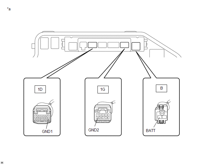
| *a | Component without semiconductor power integration ECU connected (Engine Room Relay Block and Junction Block Assembly) | - | - |
(a) Remove the semiconductor power integration ECU from the engine room relay block and junction block assembly.
Click here
(b) Measure the voltage according to the value(s) in the table below.
Standard Voltage:
| Tester Connection | Condition | Specified Condition |
|---|---|---|
| B-1 (BATT) - Body ground | Always | 11 to 14 V |
(c) Measure the resistance according to the value(s) in the table below.
Standard Resistance:
| Tester Connection | Condition | Specified Condition |
|---|---|---|
| 1D-14 (GND1) - Body ground | Always | Below 1 Ω |
| 1G-5 (GND2) - Body ground | Always | Below 1 Ω |
| NG | | REPAIR OR REPLACE HARNESS OR CONNECTOR |
|
| 4. | CHECK HARNESS AND CONNECTOR (SEMICONDUCTOR POWER INTEGRATION ECU - MAIN BODY ECU (MULTIPLEX NETWORK BODY ECU)) |
(a) Disconnect the J8 main body ECU (multiplex network body ECU) connector.
(b) Measure the resistance according to the value(s) in the table below.
Standard Resistance:
| Tester Connection | Condition | Specified Condition |
|---|---|---|
| 1D-2 (-S) - J8-1 (DIM) | Always | Below 1 Ω |
| 1D-2 (-S) or J8 -1 (DIM) - Body ground | Always | 10 kΩ or higher |
| NG | | REPAIR OR REPLACE HARNESS OR CONNECTOR |
|
| 5. | REPLACE SEMICONDUCTOR POWER INTEGRATION ECU |
(a) Replace the semiconductor power integration ECU with a new one.
Click here
|
| 6. | CHECK OPERATION (HIGH BEAM HEADLIGHTS) |
(a) Check the operation of the high beam headlights.
OK:
High beam headlights operate normally.
| OK | | END (SEMICONDUCTOR POWER INTEGRATION ECU WAS DEFECTIVE) |
| NG | | REPLACE MAIN BODY ECU (MULTIPLEX NETWORK BODY ECU) |
 Low Beam Headlight Circuit
DESCRIPTION The main body ECU (multiplex network body ECU) controls the low beam headlights. WIRING DIAGRAM CAUTION / NOTICE / HINT NOTICE:
Inspect the fuses for circuits related to this system be ...

Other materials:
Lexus RX (RX 350L, RX450h) 2016-2026 Repair Manual > Fuel Pressure Sensor (for High Pressure): Removal
REMOVAL CAUTION / NOTICE / HINT The necessary procedures (adjustment, calibration, initialization or registration) that must be performed after parts are removed and installed, or replaced during fuel pressure sensor removal/installation are shown below. Necessary Procedures After Parts Removed/Inst ...
Lexus RX (RX 350L, RX450h) 2016-2026 Owners Manual > Driving tips: Winter driving tips
Carry out the necessary preparations and inspections before driving the
vehicle
in winter. Always drive the vehicle in a manner appropriate to the prevailing
weather conditions.
Pre-winter preparations
Use fluids that are appropriate to the prevailing outside temperatures.
Engine oil
...
Lexus RX (RX 350L, RX450h) 2016-{YEAR} Owners Manual
- For your information
- Pictorial index
- For safety and security
- Instrument cluster
- Operation of each component
- Driving
- Lexus Display Audio system
- Interior features
- Maintenance and care
- When trouble arises
- Vehicle specifications
- For owners
Lexus RX (RX 350L, RX450h) 2016-{YEAR} Repair Manual

0.0115