Lexus RX (RX 350L, RX450h) 2016-2026 Repair Manual: Removal
REMOVAL
CAUTION / NOTICE / HINT
The necessary procedures (adjustment, calibration, initialization or registration) that must be performed after parts are removed and installed, or replaced during stop light switch removal/installation are shown below.
Necessary Procedures After Parts Removed/Installed/Replaced| Replaced Part or Performed Procedure | Necessary Procedure | Effect/Inoperative Function when Necessary Procedure not Performed | Link |
|---|---|---|---|
| Disconnect cable from negative battery terminal | Memorize steering angle neutral point | Lane Control System | |
| Pre-collision system | |||
| Intelligent clearance sonar system*1 | |||
| Parking Assist Monitor System | | ||
| Panoramic View Monitor System | | ||
| Lighting System (w/ Automatic Headlight Beam Level Control System) | | ||
| Initialize back door lock | Power door lock control system | | |
| Reset back door close position | Power Back Door System (w/ Outside Door Control Switch) | |
*1: When performing learning using the Techstream.
Click here .gif)
CAUTION:
Some of these service operations affect the SRS airbag system. Read the precautionary notices concerning the SRS airbag system before servicing.
Click here
.png)
HINT:
- Use the same procedure for the RH side and LH side.
- The following procedure is for the LH side.
PROCEDURE
1. REMOVE LOWER NO. 1 INSTRUMENT PANEL AIR BAG ASSEMBLY
Click here
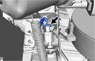
2. REMOVE STOP LIGHT SWITCH ASSEMBLY
| (a) Disconnect the connector. |
|
(b) Loosen the stop light switch lock nut and remove the stop light switch assembly as shown in the illustration.
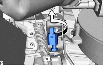
| *a | Stop Light Switch Lock Nut |
.png) | Remove in this Direction |
 On-vehicle Inspection
ON-VEHICLE INSPECTION PROCEDURE 1. INSPECT STOP LIGHT SWITCH ASSEMBLY (a) Disconnect the A55 stop light switch assembly connector. *a Front view of wire harness connector (to Stop Li ...
 Installation
INSTALLATION PROCEDURE 1. INSTALL STOP LIGHT SWITCH ASSEMBLY (a) Temporarily install the stop light switch assembly with stop light switch lock nut as shown in the illustration. *a Stop Light Sw ...
Other materials:
Lexus RX (RX 350L, RX450h) 2016-2026 Repair Manual > Electric Parking Brake System: Supply Voltage Circuit IG Open (C123A14)
DESCRIPTION DTC No. Detection Item DTC Detection Condition Trouble Area Memory Note C123A14 Supply Voltage Circuit IG Open
Diagnosis Condition:
Engine switch on (IG)
Malfunction Status:
When the ECM is communicating via CAN communication, IG power is not input to the skid c ...
Lexus RX (RX 350L, RX450h) 2016-2026 Repair Manual > Oil Pan And Oil Level Sensor: Removal
REMOVAL CAUTION / NOTICE / HINT The necessary procedures (adjustment, calibration, initialization or registration) that must be performed after parts are removed and installed, or replaced during engine oil level sensor removal/installation are shown below. Necessary Procedure After Parts Removed/In ...
Lexus RX (RX 350L, RX450h) 2016-{YEAR} Owners Manual
- For your information
- Pictorial index
- For safety and security
- Instrument cluster
- Operation of each component
- Driving
- Lexus Display Audio system
- Interior features
- Maintenance and care
- When trouble arises
- Vehicle specifications
- For owners
Lexus RX (RX 350L, RX450h) 2016-{YEAR} Repair Manual

0.0094