Lexus RX (RX 350L, RX450h) 2016-2026 Repair Manual: Removal
REMOVAL
CAUTION / NOTICE / HINT
The necessary procedures (adjustment, calibration, initialization, or registration) that must be performed after parts are removed and installed, or replaced during side television camera assembly removal/installation are shown below.
Necessary Procedure After Parts Removed/Installed/Replaced| Replaced Part or Performed Procedure | Necessary Procedure | Effect/Inoperative Function when Necessary Procedure not Performed | Link |
|---|---|---|---|
| Side television camera view adjustment | Panoramic view monitor system | |
HINT:
- Use the same procedure for the RH and LH sides.
- The following procedure is for the LH side.
PROCEDURE
1. REMOVE FRONT DOOR INSIDE HANDLE BEZEL PLUG
Click here .gif)
2. REMOVE MULTIPLEX NETWORK MASTER SWITCH ASSEMBLY WITH FRONT DOOR UPPER ARMREST BASE PANEL (for Driver Side)
Click here
3. REMOVE POWER WINDOW REGULATOR SWITCH ASSEMBLY WITH FRONT DOOR UPPER ARMREST BASE PANEL (for Front Passenger Side)
Click here
4. REMOVE DOOR ARMREST COVER
Click here
5. REMOVE COURTESY LIGHT ASSEMBLY
Click here
6. REMOVE FRONT DOOR NO. 1 STIFFENER CUSHION
Click here
7. REMOVE FRONT DOOR TRIM BOARD SUB-ASSEMBLY
Click here
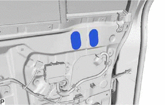
8. REMOVE OUTER MIRROR PROTECTOR
| (a) Remove the 2 outer mirror protectors. |
|
9. REMOVE OUTER MIRROR INSTALL HOLE COVER
(a) w/o Panoramic View Monitor System:
| (1) Disconnect the connector. |
|
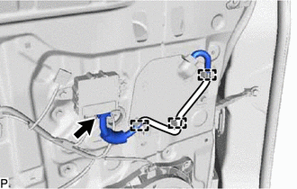
(2) Disengage the 3 clamps.
(b) w/ Panoramic View Monitor System:
| (1) Disconnect the 2 connectors. |
|
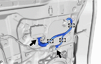
(2) Disengage the 3 clamps.
| (c) Remove the 2 screws. |
|
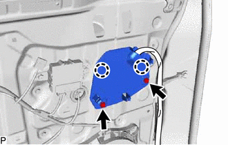
(d) Disengage the 2 claws to remove the outer mirror install hole cover.
10. REMOVE OUTER REAR VIEW MIRROR ASSEMBLY
| (a) Remove the 3 nuts. |
|
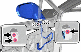
(b) Disengage the claw and 2 guides, and remove the outer rear view mirror assembly.
 Components
COMPONENTS ILLUSTRATION *A for Driver Side *B for Front Passenger Side *1 COURTESY LIGHT ASSEMBLY *2 DOOR ARMREST COVER *3 FRONT DOOR INSIDE HANDLE BEZEL PLUG *4 FRONT DO ...
 Inspection
INSPECTION PROCEDURE 1. INSPECT OUTER REAR VIEW MIRROR ASSEMBLY RH (a) Check the operation of the mirror surface. NOTICE: If the mirror surface is fully turned to the right, left, upward or downward p ...
Other materials:
Lexus RX (RX 350L, RX450h) 2016-2026 Repair Manual > Steering Lock System: IG2 Signal Malfunction (B2788)
DESCRIPTION This DTC is stored when the steering lock ECU (steering lock actuator or upper bracket assembly) detects an IG2 power supply malfunction. HINT: The steering lock ECU (steering lock actuator or upper bracket assembly) is not connected to the CAN communication system. However, the steering ...
Lexus RX (RX 350L, RX450h) 2016-2026 Repair Manual > Lane Control System: Dtc Check / Clear
DTC CHECK / CLEAR CHECK FOR DTC (a) Connect the Techstream to the DLC3. (b) Turn the engine switch on (IG). (c) Turn the Techstream on. (d) Enter the following menus: Chassis / Lane Control / Trouble Codes. Chassis > Lane Control > Trouble Codes (e) Check for DTCs (Test Failed / Pending / Conf ...
Lexus RX (RX 350L, RX450h) 2016-{YEAR} Owners Manual
- For your information
- Pictorial index
- For safety and security
- Instrument cluster
- Operation of each component
- Driving
- Lexus Display Audio system
- Interior features
- Maintenance and care
- When trouble arises
- Vehicle specifications
- For owners
Lexus RX (RX 350L, RX450h) 2016-{YEAR} Repair Manual

0.0135