Lexus RX (RX 350L, RX450h) 2016-2026 Repair Manual: Reassembly
REASSEMBLY
CAUTION / NOTICE / HINT
HINT:
- Use the same procedure for the RH side and LH side.
- The following procedure is for the LH side.
PROCEDURE
1. INSTALL OUTER MIRROR RETRACTOR LH (w/ Power Retract Mirror)
(a) Install a new frame sub-assembly to the support as shown in the illustration.
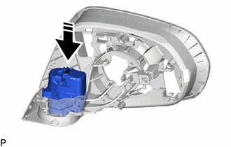
.png) | Install in this Direction |
| (b) Install the 2 screws. |
|
.png)
(c) Pass a new wire harness sub-assembly through the frame sub-assembly as shown in the illustration.
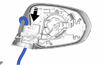
| | Install in this Direction |
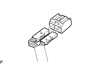
| (d) Connect the 2 connectors. |
|
.png)
| (e) Engage the clamp. |
|
.png)
(f) Connect the connector.
| (g) Install the actuator sub-assembly with the 3 screws. |
|
.png)
(h) Pass the wire harness sub-assembly through the base sub-assembly as shown in the illustration.
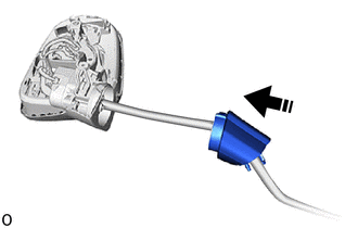
| | Install in this Direction |
| (i) Using a T25 "TORX" socket wrench, install the base sub-assembly with 3 new screws. NOTICE: When installing the base sub-assembly, check that the wire harness sub-assembly is not caught between the base sub-assembly and body. Failure to do so may cause a short circuit. |
|
.png)
| (j) Pass the wire harness sub-assembly through a new gasket sub-assembly and engage the 6 guides to install the gasket sub-assembly. NOTICE: Make sure there is no clearance between the gasket sub-assembly and base sub-assembly. |
|
.png)
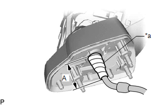
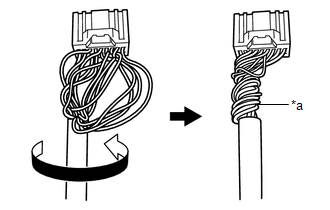
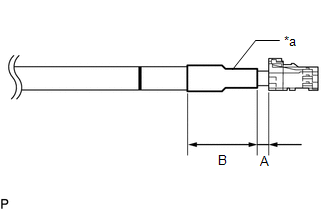
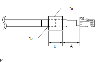
(k) Adjust the wire harness sub-assembly so that the marking is at the position shown in the illustration.
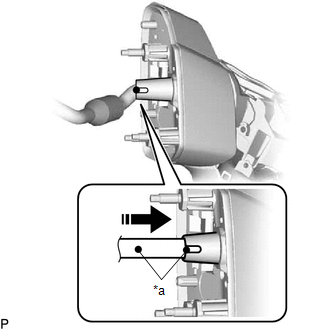
| *a | Marking |
| | Install in this Direction |
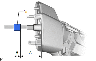
| (l) Wind vinyl tape around the wire harness sub-assembly to secure it. Reference Measurement
|
|
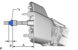
| (m) Wind sponge tape around the wire harness sub-assembly to secure it. Reference Measurement
|
|
| (n) Wind vinyl tape around the wire harness sub-assembly to secure it. Reference Measurement
|
|
(o) Set the retainer of a new connector housing to the unlock position.
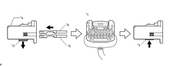
| *a | Connector Housing | *b | Wire Harness Pin |
| *c | Back View of Wire Harness Connector | *d | Retainer Unlock Position |
| *e | Retainer Lock Position | - | - |
(p) Insert new wire harness pins from the backside of the adapter until they lock.
Wire Harness Color Chart:
| 1 | 2 | 3 | 4 | 5 | 6 | 7 | 8 |
|---|---|---|---|---|---|---|---|
| PURPLE | - | SKY BLUE | BLACK-GREEN | ORANGE | WHITE-BLACK | BLUE-YELLOW | BLACK-WHITE |
Wire Harness Color Chart:
| 9 | 10 | 11 | 12 | 13 | 14 | 15 | 16 |
|---|---|---|---|---|---|---|---|
| BROWN | RED | LIGHT GREEN | WHITE | YELLOW-BLACK | GRAY | BLACK-RED | PINK |
(q) Set the retainer to the lock position.
NOTICE:
- When inserting the wire harness pins, compare with the connector that was cut off during removal to verify the insertion positions, and then make sure to insert the pins of the correct wire colors in the correct positions.
- Make sure that the wire harness pins are securely locked in position and cannot be removed.
- The wire harness pins cannot be removed after they have locked into place, so be absolutely certain to insert them in the correct positions.
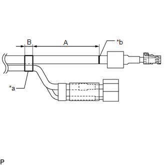
| (r) Route the longer part of the wire harness sub-assembly as shown in the illustration. |
|
(s) w/ Panoramic View Monitor System:
| (1) Connect each connector to a new adapter. |
|
| (2) Route the longer part of the wire harness sub-assembly as shown in the illustration. |
|
| (t) Wind vinyl tape around the wire harness sub-assembly to secure it. Reference Measurement
|
|
| (u) Wind sponge tape around the wire harness sub-assembly to secure it. Reference Measurement
|
|
(v) w/ Panoramic View Monitor System:
| (1) Wind vinyl tape around the wire harness sub-assembly to secure it. Reference Measurement
|
|
| (w) Engage the 2 guides and 2 claws. |
|
.png)
(x) Install the clamp with the screw.
2. INSTALL OUTER MIRROR ACTUATOR ASSEMBLY (for TMMC Made)
| (a) Connect the connector. NOTICE: Be careful not to bend the terminals of the connector. |
|
| (b) Engage the clamp. |
|
.png)
| (c) Connect the connector. |
|
.png)
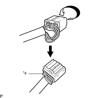
| (d) Install the connector cover. |
|
.png)
| (e) Engage the clamp. |
|
.png)
(f) Engage the guide as shown in the illustration.
| | Install in this Direction |
| (g) Install the outer mirror actuator assembly with the 3 screws. |
|
.png)
3. INSTALL SIDE TURN SIGNAL LIGHT ASSEMBLY
Click here .gif)
4. INSTALL OUTER MIRROR HOLE COVER
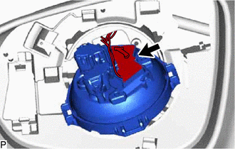
| (a) Engage the 2 guides and 3 claws to install the outer mirror hole cover. |
|
.png)
(b) Install the screw.
(c) w/ Panoramic View Monitor System:
| (1) Connect the connector. |
|
.png)
(2) Engage the clamp.
5. INSTALL NO. 2 OUTER MIRROR COVER
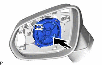
| (a) Engage the guide and 5 claws to install the No. 2 outer mirror cover. |
|
.png)
(b) Install the screw.
6. INSTALL NO. 1 OUTER MIRROR COVER
Click here
7. INSTALL OUTER MIRROR
Click here
 Installation
INSTALLATION CAUTION / NOTICE / HINT HINT:
Use the same procedure for the RH side and LH side.
The following procedure is for the LH side.
PROCEDURE 1. INSTALL OUTER REAR VIEW MIRROR ASSEMBLY ...
 Outer Rear View Mirror Cover
ComponentsCOMPONENTS ILLUSTRATION *1 NO. 1 OUTER MIRROR COVER *2 OUTER MIRROR RemovalREMOVAL CAUTION / NOTICE / HINT HINT:
Use the same procedure for the RH side and LH side.
The fol ...
Other materials:
Lexus RX (RX 350L, RX450h) 2016-2026 Repair Manual > Power Tilt And Power Telescopic Steering Column System: Freeze Frame Data
FREEZE FRAME DATA FREEZE FRAME DATA NOTICE:
Freeze frame data values will vary depending on the measurement conditions, surroundings, or vehicle conditions. For this reason, there may be a problem even when the values are within specifications.
Turn the engine switch on (IG) and park the vehicl ...
Lexus RX (RX 350L, RX450h) 2016-2026 Repair Manual > Fuel Sender Gauge Assembly: Inspection
INSPECTION PROCEDURE 1. INSPECT FUEL SENDER GAUGE ASSEMBLY (a) Check that the float moves smoothly between F and E. (b) Check the fuel sender gauge assembly voltage. (1) Apply 5 V between terminals 2 and 3. NOTICE:
Be careful when connecting the leads, as the fuel sender gauge assembly may b ...
Lexus RX (RX 350L, RX450h) 2016-{YEAR} Owners Manual
- For your information
- Pictorial index
- For safety and security
- Instrument cluster
- Operation of each component
- Driving
- Lexus Display Audio system
- Interior features
- Maintenance and care
- When trouble arises
- Vehicle specifications
- For owners
Lexus RX (RX 350L, RX450h) 2016-{YEAR} Repair Manual

0.0122