Lexus RX (RX 350L, RX450h) 2016-2026 Repair Manual: Terminals Of Ecu
TERMINALS OF ECU
CHECK OUTER MIRROR CONTROL ECU ASSEMBLY (DRIVER DOOR)
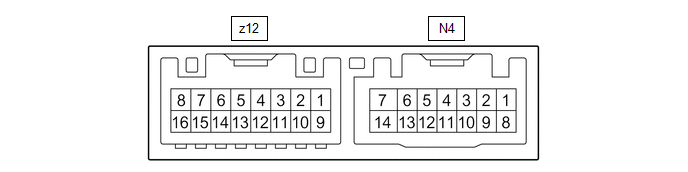
(a) Disconnect the N4 outer mirror control ECU assembly (driver door) connector.
(b) Measure the voltage and resistance according to the value(s) in the table below.
HINT:
Measure the values on the wire harness side with the connector disconnected.
| Terminal No. (Symbol) | Wiring Color | Terminal Description | Condition | Specified Condition |
|---|---|---|---|---|
| N4-14 (BDR) - Body ground | L - Body ground | +B power supply | Always | 11 to 14 V |
| N4-6 (CPUB) - Body ground | L - Body ground | +B power supply | Always | 11 to 14 V |
| N4-5 (SIG) - Body ground | Y - Body ground | Ignition power supply | Engine switch off → on (IG) | Below 1 V → 11 to 14 V |
| N4-7 (GND) - Body ground | W-B - Body ground | Ground | Always | Below 1 Ω |
(c) Reconnect the N4 outer mirror control ECU assembly (driver door) connector.
(d) Measure the voltage according to the value(s) in the table below.
| Terminal No. (Symbol) | Wiring Color | Terminal Description | Condition | Specified Condition |
|---|---|---|---|---|
| z12-3 (MR) - Body ground | SB - Body ground | Power retract mirror motor drive voltage | Outer rear view mirror assembly (driver door) being retracted | 11 to 14 V |
| Outer rear view mirror assembly (driver door) stopped | Below 1 V | |||
| z12-11 (MF) - Body ground | LG - Body ground | Power retract mirror motor drive voltage | Outer rear view mirror assembly (driver door) returning | 11 to 14 V |
| Outer rear view mirror assembly (driver door) stopped | Below 1 V | |||
| z12-1 (MV) - z12-10 (M+) | V - R | Vertical mirror motor drive voltage | Driver door mirror surface moving upward → stopped | 11 to 14 V → Below 1 V |
| z12-10 (M+) - z12-1 (MV) | R - V | Vertical mirror motor drive voltage | Driver door mirror surface moving downward → stopped | 11 to 14 V → Below 1 V |
| z12-10 (M+) - z12-9 (MH) | R - BR | Horizontal mirror motor drive voltage | Driver door mirror surface moving right → stopped | 11 to 14 V → Below 1 V |
| z12-9 (MH) - z12-10 (M+) | BR - R | Horizontal mirror motor drive voltage | Driver door mirror surface moving left → stopped | 11 to 14 V → Below 1 V |
| z12-4 (HTR+) - z12-12 (TRN-) | B-G - W | Mirror heater relay drive voltage | Mirror heater switch (rear window defogger switch) on | 11 to 14 V |
| z12-5 (VDD) - N4-7 (GND) | O - W-B | Mirror position sensor power supply | Engine switch on (IG) | 4.75 to 5.25 V |
| z12-6 (VSSR) - N4-7 (GND) | W-B - W-B | Mirror position sensor signal | Engine switch on (IG) | 0 to 5 V |
| z12-13 (HSSR) - N4-7 (GND) | Y-B - W-B | Mirror position sensor signal | Engine switch on (IG) | 0 to 5 V |
| z12-7 (EC+) - z12-15 (EC-) | L-Y - B-R | Automatic glare-resistant EC mirror drive signal | Automatic glare-resistant EC mirror on | 1.05 to 1.35 V |
| Automatic glare-resistant EC mirror off | Below 1 V | |||
| N4-4 (M3) - N4-7 (GND) | R - W-B | M3 switch signal for seat memory switch | M3 switch on | Below 1 V |
| M3 switch off | 11 to 14 V | |||
| N4-3 (M2) - N4-7 (GND) | V - W-B | M2 switch signal for seat memory switch | M2 switch on | Below 1 V |
| M2 switch off | 11 to 14 V | |||
| N4-2 (M1) - N4-7 (GND) | G - W-B | M1 switch signal for seat memory switch | M1 switch on | Below 1 V |
| M1 switch off | 11 to 14 V | |||
| N4-1 (MM) - N4-7 (GND) | W - W-B | SET switch signal for seat memory switch | SET switch on | Below 1 V |
| SET switch off | 11 to 14 V |
CHECK OUTER MIRROR CONTROL ECU ASSEMBLY (FRONT PASSENGER DOOR)
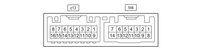
(a) Disconnect the M4 outer mirror control ECU assembly (front passenger door) connector.
(b) Measure the voltage and resistance according to the value(s) in the table below.
HINT:
Measure the values on the wire harness side with the connector disconnected.
| Terminal No. (Symbol) | Wiring Color | Terminal Description | Condition | Specified Condition |
|---|---|---|---|---|
| M4-14 (BDR) - Body ground | G - Body ground | +B power supply | Always | 11 to 14 V |
| M4-6 (CPUB) - Body ground | GR - Body ground | +B power supply | Always | 11 to 14 V |
| M4-5 (SIG) - Body ground | B - Body ground | Ignition power supply | Engine switch off → on (IG) | Below 1 V → 11 to 14 V |
| M4-7 (GND) - Body ground | W-B - Body ground | Ground | Always | Below 1 Ω |
(c) Reconnect the M4 outer mirror control ECU assembly (front passenger door) connector.
(d) Measure the voltage according to the value(s) in the table below.
| Terminal No. (Symbol) | Wiring Color | Terminal Description | Condition | Specified Condition |
|---|---|---|---|---|
| z13-3 (MR) - Body ground | SB - Body ground | Power retract mirror motor drive voltage | Outer rear view mirror assembly (front passenger door) being retracted | 11 to 14 V |
| Outer rear view mirror assembly (front passenger door) stopped | Below 1 V | |||
| z13-11 (MF) - Body ground | LG - Body ground | Power retract mirror motor drive voltage | Outer rear view mirror assembly (front passenger door) returning | 11 to 14 V |
| Outer rear view mirror assembly (front passenger door) stopped | Below 1 V | |||
| z13-1 (MV) - z13-10 (M+) | V - R | Vertical mirror motor drive voltage | Front passenger door mirror surface moving upward → stopped | 11 to 14 V → Below 1 V |
| z13-10 (M+) - z13-1 (MV) | R - V | Vertical mirror motor drive voltage | Front passenger door mirror surface moving downward → stopped | 11 to 14 V → Below 1 V |
| z13-10 (M+) - z13-9 (MH) | R - BR | Horizontal mirror motor drive voltage | Front passenger door mirror surface moving right → stopped | 11 to 14 V → Below 1 V |
| z13-9 (MH) - z13-10 (M+) | BR - R | Horizontal mirror motor drive voltage | Front passenger door mirror surface moving left → stopped | 11 to 14 V → Below 1 V |
| z13-4 (HTR+) - z13-12 (TRN-) | B-G - W | Mirror heater relay drive voltage | Mirror heater switch (rear window defogger switch) on | 11 to 14 V |
| z13-5 (VDD) - M4-7 (GND) | O - W-B | Mirror position sensor power supply | Engine switch on (IG) | 4.75 to 5.25 V |
| z13-6 (VSSR) - M4-7 (GND) | W-B - W-B | Mirror position sensor signal | Engine switch on (IG) | 0 to 5 V |
| z13-13 (HSSR) - M4-7 (GND) | Y-B - W-B | Mirror position sensor signal | Engine switch on (IG) | 0 to 5 V |
| z13-7 (EC+) - z13-15 (EC-) | L-T - B-R | Automatic glare-resistant EC mirror drive signal | Automatic glare-resistant EC mirror on | 1.05 to 1.35 V |
| Automatic glare-resistant EC mirror off | Below 1 V |
 Problem Symptoms Table
PROBLEM SYMPTOMS TABLE NOTICE: If the battery voltage is low, the mirror heater function may not operate. When "Operation of Electrical Items Restricted." is displayed on the multi-information display ...
 Diagnosis System
DIAGNOSIS SYSTEM CHECK DLC3 (a) Check the DLC3. Click here INSPECT BATTERY VOLTAGE (a) Measure the battery voltage. Standard Voltage: 11 to 14 V If the voltage is below 11 V, recharge or replace th ...
Other materials:
Lexus RX (RX 350L, RX450h) 2016-2026 Repair Manual > Rear No. 2 Seat Outer Belt Assembly: Removal
REMOVAL CAUTION / NOTICE / HINT HINT:
Use the same procedure for the RH side and LH side.
The following procedure is for the LH side.
PROCEDURE 1. REMOVE REAR NO. 2 SEAT ASSEMBLY Click here 2. REMOVE REAR DOOR SCUFF PLATE Click here 3. REMOVE REAR DOOR INSIDE SCUFF PLATE Click here 4 ...
Lexus RX (RX 350L, RX450h) 2016-2026 Repair Manual > Sfi System: Thermostat Heater Control Circuit Short to Ground or Open (P059714)
DESCRIPTION Refer to DTC P059712. Click here DTC No. Detection Item DTC Detection Condition Trouble Area MIL Memory Note P059714 Thermostat Heater Control Circuit Short to Ground or Open Open or short in thermostat heater circuit and power supply circuit (1 trip detection lo ...
Lexus RX (RX 350L, RX450h) 2016-{YEAR} Owners Manual
- For your information
- Pictorial index
- For safety and security
- Instrument cluster
- Operation of each component
- Driving
- Lexus Display Audio system
- Interior features
- Maintenance and care
- When trouble arises
- Vehicle specifications
- For owners
Lexus RX (RX 350L, RX450h) 2016-{YEAR} Repair Manual

0.0138