Lexus RX (RX 350L, RX450h) 2016-2026 Repair Manual: Terminals Of Ecu
TERMINALS OF ECU
HINT:
Check from the rear of the connector while it is connected to the components.
RADIO RECEIVER ASSEMBLY
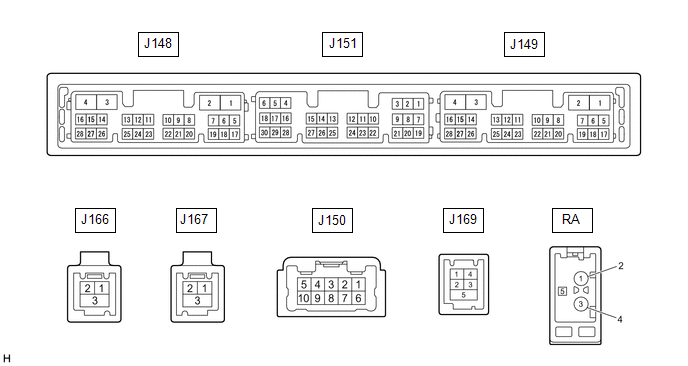
| Terminal No. (Symbol) | Wiring Color | Terminal Description | Condition | Specified Condition |
|---|---|---|---|---|
| J150-1 (FR+) - J148-1 (GND1) | R - W-B | Sound signal (Right) | Audio system playing | A waveform synchronized with sound signals is output |
| J150-2 (FL+) - J148-1 (GND1) | B - W-B | Sound signal (Left) | Audio system playing | A waveform synchronized with sound signals is output |
| J150-3 (RL+) - J148-1 (GND1) | V - W-B | Voice signal | Voice guidance sounding | A waveform synchronized with voice signals is output |
| J150-6 (FR-) - J148-1 (GND1) | G - W-B | Sound signal (Right) | Audio system playing | A waveform synchronized with sound signals is output |
| J150-7 (FL-) - J148-1 (GND1) | W - W-B | Sound signal (Left) | Audio system playing | A waveform synchronized with sound signals is output |
| J150-8 (RL-) - J148-1 (GND1) | SB - W-B | Voice signal | Audio system playing | A waveform synchronized with sound signals is output |
| J148-1 (GND1) - Body ground | W-B - Body ground | Ground | Always | Below 1 Ω |
| J148-2 (GND2) - Body ground | R - Body ground | Ground | Always | Below 1 Ω |
| J148-3 (+B) - J148-1 (GND1) | B - W-B | Power source (+B) | Always | 11 to 14 V |
| J148-4 (+B1) - J148-1 (GND1) | BE - W-B | Power source (+B) | Always | 11 to 14 V |
| J148-5 (TX1+) | GR | AVC-LAN communication signal | - | - |
| J148-6 (TX1-) | V | AVC-LAN communication signal | - | - |
| J148-10 (AGND) - Body ground | Shielded - Body ground | Shield ground | Always | Below 1 Ω |
| J148-11 (VAL+) - J148-13 (VA-) | G - P | Sound signal (Left) | External device playing (When stereo jack used) | A waveform synchronized with sound signals is output |
| J148-12 (VAR+) - J148-13 (VA-) | L - P | Sound signal (Right) | External device playing (When stereo jack used) | A waveform synchronized with sound signals is output |
| J148-13 (VA-) - J148-1 (GND1) | P - W-B | Ground | Always | Below 1 V |
| J148-14 (ADPG) - J148-1 (GND1) | BE - W-B | External device connection detection signal | External device connected | Below 1 V |
| External device not connected | 1.1 to 1.9 V | |||
| J148-15 (ACC1) - J148-1 (GND1) | SB - W-B | Power source (ACC) | Engine switch off | Below 1 V |
| Engine switch on (ACC) | 11 to 14 V | |||
| J148-16 (ACC) - J148-1 (GND1) | L - W-B | Power source (ACC) | Engine switch on (ACC) | 11 to 14 V |
| Engine switch off | Below 1 V | |||
| J148-17 (TX2+) | P | AVC-LAN communication signal | - | - |
| J148-18 (TX2-) | Y | AVC-LAN communication signal | - | - |
| J148-21 (SW1) - J148-24 (SWG) | V - L | Steering pad switch signal | No switch pushed | 2.97 to 3.56 V |
| Seek+ switch pushed | 0.27 to 0.35 V | |||
| Seek- switch pushed | 0.86 to 1.03 V | |||
| Volume+ switch pushed | 1.51 to 1.79 V | |||
| Volume- switch pushed | 2.22 to 2.66 V | |||
| J148-22 (SW2) - J148-24 (SWG) | G - L | Steering pad switch signal | No switch pushed | 2.97 to 3.56 V |
| MODE switch pushed | 0.27 to 0.35 V | |||
| On hook switch pushed | 0.86 to 1.03 V | |||
| Off hook switch pushed | 1.51 to 1.79 V | |||
| Voice switch pushed | 2.22 to 2.66 V | |||
| J148-24 (SWG) - Body ground | L - Body ground | Steering pad switch ground | Always | Below 1 Ω |
| J148-25 (MUT1) - J148-1 (GND1) | LG - W-B | Mute signal | Audio system playing | 2.0 V or higher |
| Audio system changing modes | Below 1 V | |||
| J148-27 (SPD) - J148-1 (GND1) | SB - W-B | Vehicle speed signal | See "Check Vehicle Signal" in Operation Check Click here | - |
| J151-1 (VMTF) - J148-1 (GND1) | Y - W-B | Visual mute signal | Engine switch on (ACC) Screen display changing | 3.5 V or higher → Below 1 V → 3.5 V or higher |
| J151-5 (CNH1) | V | Local bus communication signal | - | - |
| J151-6 (CNL1) | W | Local bus communication signal | - | - |
| J151-13 (CANH) | BE | CAN communication signal | - | - |
| J151-14 (CANL) | W | CAN communication signal | - | - |
| J151-15 (ILL+) - J148-1 (GND1) | V - W-B | Illumination signal | Light control switch off | Below 1 V |
| Light control switch in tail or head position | 11 to 14 V | |||
| J151-16 (ILL-) - J148-1 (GND1) | W - W-B | Illumination signal | Light control switch off | Below 1 V |
| Light control switch in tail or head position | Pulse generation | |||
| J151-19 (IG) - J148-1 (GND1) | L - W-B | Power source (IG) | Engine switch off | Below 1 V |
| Engine switch on (IG) | 11 to 14 V | |||
| J151-21 (MIN+) - J148-1 (GND1) | R - W-B*1 P - W-B*2 | Microphone voice signal | See "Check Microphone" in Operation Check Click here | - |
| J151-22 (MIN-) - J148-1 (GND1) | G - W-B | Microphone voice signal | See "Check Microphone" in Operation Check Click here | - |
| J151-23 (MACC) - J148-1 (GND1)*2 | L - W-B | Microphone power supply | Engine switch off | Below 1 V |
| Engine switch on (ACC) | 4 to 6 V | |||
| J151-24 (SGND) - Body ground | Shielded - Body ground | Shield ground | Always | Below 1 Ω |
| J151-25 (SNS2) - J148-1 (GND1) | SB - W-B | Microphone connection detection signal | Always | Below 1 V |
| J169-1 (USV1) | - | Power source | - | - |
| J169-2 (US1-) | - | Data signal | - | - |
| J169-3 (US1+) | - | Data signal | - | - |
| J169-4 (UGD1) | - | Ground | - | - |
| J169-5 (USG1) | - | Shield ground | - | - |
| J167-1 (USB+)*1 | - | Data signal | - | - |
| J167-2 (USB-)*1 | - | Data signal | - | - |
| J167-3 (USBS)*1 | - | Ground | - | - |
| J166-1 (GVI-) | - | Video signal (Digital) | - | - |
| J166-2 (GVI+) | - | Video signal (Digital) | - | - |
| J166-3 (GVG1) | Shielded | Shield ground | - | - |
| J149-10 (USBV) - J149-11 (USBG)*1 | L - G | DCM (telematics transceiver) power supply | Engine switch off | Below 1 V |
| Engine switch on (ACC) | 4.75 to 5.25 V | |||
| J149-11 (USBG) - Body ground*1 | G | Ground | Always | Below 1 Ω |
| RA-5 (ANT+) - J148-1 (GND1) | - - W-B | Power source of antenna | Engine switch on (ACC) Radio switch on and FM or AM selected | 11 to 14 V |
- *1: w/ Manual (SOS) Switch
- *2: w/o Manual (SOS) Switch
STEREO COMPONENT AMPLIFIER ASSEMBLY
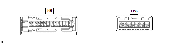
| Terminal No. (Symbol) | Wiring Color | Terminal Description | Condition | Specified Condition |
|---|---|---|---|---|
| J66-1 (+B) - J66-3 (GND) | P - W-B | Power source (+B) | Always | 11 to 14 V |
| J66-3 (GND) - Body ground | W-B - Body ground | Ground | Always | Below 1 V |
| J66-4 (WFL+) - J66-3 (GND) | L - W-B | Sound signal (Front Left) | Audio system playing | A waveform synchronized with sound signals is output |
| J66-5 (WFR+) - J66-3 (GND) | G - W-B | Sound signal (Front Right) | Audio system playing | A waveform synchronized with sound signals is output |
| J66-6 (WF1+) - J66-3 (GND)*1 | GR - W-B | Sound signal (Woofer) | Audio system playing | A waveform synchronized with sound signals is output |
| J66-7 (CTR+) - J66-3 (GND) | L - W-B | Sound signal (Front Center) | Audio system playing | A waveform synchronized with sound signals is output |
| J66-8 (RL+) - J66-3 (GND) | B - W-B | Sound signal (Rear Left) | Audio system playing | A waveform synchronized with sound signals is output |
| J66-9 (RR+) - J66-3 (GND) | R - W-B | Sound signal (Rear Right) | Audio system playing | A waveform synchronized with sound signals is output |
| J66-12 (FL+) - J66-3 (GND) | R - W-B | Sound signal (Front Left) | Audio system playing | A waveform synchronized with sound signals is output |
| J66-13 (FR+) - J66-3 (GND) | LG - W-B | Sound signal (Front Right) | Audio system playing | A waveform synchronized with sound signals is output |
| J66-16 (+B2) - J66-3 (GND) | L - W-B | Power source (+B) | Always | 11 to 14 V |
| J66-18 (GND2) - Body ground | W-B - Body ground | Ground | Always | Below 1 V |
| J66-19 (WFL-) - J66-3 (GND) | LG - W-B | Sound signal (Front Left) | Audio system playing | A waveform synchronized with sound signals is output |
| J66-20 (WFR-) - J66-3 (GND) | R - W-B | Sound signal (Front Right) | Audio system playing | A waveform synchronized with sound signals is output |
| J66-21 (WF1-) - J66-3 (GND)*1 | W - W-B | Sound signal (Woofer) | Audio system playing | A waveform synchronized with sound signals is output |
| J66-22 (CTR-) - J66-3 (GND) | V - W-B*2 P - W-B*3 | Sound signal (Front Center) | Audio system playing | A waveform synchronized with sound signals is output |
| J66-23 (RL-) - J66-3 (GND) | Y - W-B | Sound signal (Rear Left) | Audio system playing | A waveform synchronized with sound signals is output |
| J66-24 (RR-) - J66-3 (GND) | W - W-B | Sound signal (Rear Right) | Audio system playing | A waveform synchronized with sound signals is output |
| J66-27 (FL-) - J66-3 (GND) | BR - W-B | Sound signal (Front Left) | Audio system playing | A waveform synchronized with sound signals is output |
| J66-28 (FR-) - J66-3 (GND) | L - W-B | Sound signal (Front Right) | Audio system playing | A waveform synchronized with sound signals is output |
| J156-1 (MUTE) - J66-3 (GND) | LG - W-B | Mute signal | Engine switch on (ACC) Audio system playing | 2.0 V or higher |
| Audio system changing modes | Below 1 V | |||
| J156-2 (L-) - J66-3 (GND) | W - W-B | Sound signal (Left) | Audio system playing | A waveform synchronized with sound signals is output |
| J156-3 (L+) - J66-3 (GND) | B - W-B | Sound signal (Left) | Audio system playing | A waveform synchronized with sound signals is output |
| J156-4 (R-) - J66-3 (GND) | G - W-B | Sound signal (Right) | Audio system playing | A waveform synchronized with sound signals is output |
| J156-5 (R+) - J66-3 (GND) | R - W-B | Sound signal (Right) | Audio system playing | A waveform synchronized with sound signals is output |
| J156-6 (SLD) - Body ground | Shield - Body ground | Shield ground | Always | Below 1 V |
| J156-7 (TX-) | Y | AVC-LAN communication signal | - | - |
| J156-8 (TX+) | P | AVC-LAN communication signal | - | - |
| J156-11 (SPD) - J66-3 (GND) | Y - W-B | Vehicle speed signal | Engine switch on (IG) Wheel being rotated | Pulse generation |
| J156-12 (ACC) - J66-3 (GND) | G - W-B | Power source (ACC) | Engine switch off | Below 1 V |
| Engine switch on (ACC) | 11 to 14 V | |||
| J156-14 (II1-) - J66-3 (GND) | SB - W-B | Voice signal | Voice guidance sounding | A waveform synchronized with voice signals is output |
| J156-15 (II1+) - J66-3 (GND) | V - W-B | Voice signal | Voice guidance sounding | A waveform synchronized with voice signals is output |
| J156-18 (SLD1) - Body ground | Shield - Body ground | Shield ground | Always | Below 1 V |
| J156-24 (TMUT) - J66-3 (GND)*2 | BE - W-B | Mute signal | Engine switch on (ACC) Audio system playing | 2.0 V or higher |
| Emergency call mode | Below 1 V |
- *1: for 12 Speakers
- *2: w/ Manual (SOS) Switch
- *3: w/o Manual (SOS) Switch
MULTI-DISPLAY ASSEMBLY

| Terminal No. (Symbol) | Wiring Color | Terminal Description | Condition | Specified Condition |
|---|---|---|---|---|
| J56-2 (ILL) - J56-13 (GND1) | LG - LA | Illumination signal | Light control switch off | Below 1 V |
| Light control switch in tail or head position | 11 to 14 V | |||
| J56-7 (TX+) | GR | AVC-LAN communication signal | - | - |
| J56-8 (V+) - J56-9 (V-) | W - R | Video signal | Engine switch on (IG) Shift lever in R Camera lens not covered, displaying image | Pulse generation (Refer to waveform 1) |
| Engine switch on (IG) Shift lever in R Camera lens covered, blacking out screen | Pulse generation (Refer to waveform 2) | |||
| J56-9 (V-) - J56-13 (GND1) | R - LA | Ground | Always | Below 1 V |
| J56-10 (CA+) - J56-21(CGND) | B - G | Rear television camera assembly power supply | Engine switch on (ACC) | 5.5 to 7.05 V |
| J56-11 (VMT1) - J56-13 (GND1) | Y - LA | Visual mute signal | When image on display switches | 3.5 V or higher → Below 1 V → 3.5 V or higher |
| J56-12 (B) - J56-13 (GND1) | LA-B - LA | Power source (+B) | Always | 11 to 14 V |
| J56-13 (GND1) - Body ground | LA - Body ground | Ground | Always | Below 1 Ω |
| J56-19 (TX-) | V | AVC-LAN communication signal | - | - |
| J56-20 (CSLD) - Body ground | Shielded - Body ground | Shield ground | Always | Below 1 Ω |
| J56-21 (CGND) - Body ground | G - Body ground | Camera ground | Always | Below 1 Ω |
| J56-24 (ACC) - J56-13 (GND1) | BE - LA | Power source (ACC) | Engine switch off | Below 1 V |
| Engine switch on (ACC) | 11 to 14 V | |||
| J165-1 (GV+) | - | Video signal (Digital) | - | - |
| J165-2 (GV-) | - | Video signal (Digital) | - | - |
| J165-3 (GVG) | Shielded | Shield ground | - | - |
(a) Reference (Oscilloscope waveform):
(1) Waveform 1 (camera lens not covered, displaying an image)
| Item | Content |
|---|---|
| Measurement terminal | J56-8 (V+) - J56-9 (V-) |
| Measurement setting | 200 mV/DIV., 50 μs/DIV. |
| Condition | Engine switch on (IG), shift lever in R |
HINT:
- The video waveform changes according to the image sent by the rear television camera assembly.
- The video waveform is constantly output when the Engine switch is on (ACC).
.png)
| *a | Waveform 1 (camera lens is not covered, displaying an image) |
| *b | Waveform 2 (camera lens is covered, blacking out the screen) |
| *c | Synchronization Signal |
| *d | Video Waveform |
(2) Waveform 2 (camera lens covered, blacking out the screen)
| Item | Content |
|---|---|
| Measurement terminal | J56-8 (V+) - J56-9 (V-) |
| Measurement setting | 200 mV/DIV., 50 μs/DIV. |
| Condition | Engine switch on (IG), shift lever in R |
HINT:
- The video waveform changes according to the image sent by the rear television camera assembly.
- The video waveform is constantly output when the Engine switch is on (ACC).
REMOTE TOUCH (REMOTE OPERATION CONTROLLER ASSEMBLY)

| Terminal No. (Symbol) | Wiring Color | Terminal Description | Condition | Specified Condition |
|---|---|---|---|---|
| J154-1 (+B) - J154-10 (GND) | LA-SB - W-B | Power source (+B) | Always | 11 to 14 V |
| J154-2 (ILL+) - J154-10 (GND) | V - W-B | Illumination signal | Light control switch off | Below 1 V |
| Light control switch in tail or head position | 11 to 14 V | |||
| J154-5 (ILL-) - J154-10 (GND) | B - W-B | Illumination signal | Light control switch off | Below 1 V |
| Light control switch in tail or head position | Pulse generation | |||
| J154-6 (ACC) - J154-10 (GND) | R - W-B | Power source (ACC) | Engine switch off | Below 1 V |
| Engine switch on (ACC) | 11 to 14 V | |||
| J154-8 (MO-) | W | Local bus communication signal | - | - |
| J154-9 (MO+) | P | Local bus communication signal | - | - |
| J154-10 (GND) - Body ground | W-B - Body ground | Ground | Always | Below 1 Ω |
CLOCK ASSEMBLY

| Terminal No. (Symbol) | Wiring Color | Terminal Description | Condition | Specified Condition |
|---|---|---|---|---|
| J79-1 (B) - J79-7 (E) | P - W-B | Power source (+B) | Always | 11 to 14 V |
| J79-2 (ACC) - J79-7 (E) | LG - W-B | Power source (ACC) | Engine switch off | Below 1 V |
| Engine switch on (ACC) | 11 to 14 V | |||
| J79-5 (TX+1) | Y | Local bus communication signal | - | - |
| J79-6 (TX-1) | W | Local bus communication signal | - | - |
| J79-7 (E) - Body ground | W-B - Body ground | Ground | Always | Below 1 V |
COMBINATION METER ASSEMBLY
Click here .gif)
HEADUP DISPLAY (METER MIRROR SUB-ASSEMBLY) (w/ Headup Display System)
Click here
DCM (TELEMATICS TRANSCEIVER) (w/ Manual (SOS) Switch)
Click here
REAR TELEVISION CAMERA ASSEMBLY
Click here
 Operation Check
OPERATION CHECK REMOTE TOUCH (REMOTE OPERATION CONTROLLER ASSEMBLY) SELF CHECK NOTICE:
Before entering self-diagnostic mode, make sure there are no obstructions which may interfere with operation o ...
 Dtc Check / Clear
DTC CHECK / CLEAR CHECK DTC (CHECK USING TECHSTREAM) (a) Connect the Techstream to the DLC3. (b) Turn the engine switch on (IG) and wait for 90 seconds. (c) Turn the Techstream on. (d) Enter the follo ...
Other materials:
Lexus RX (RX 350L, RX450h) 2016-2026 Repair Manual > Oil And Oil Filter: Replacement
REPLACEMENT CAUTION / NOTICE / HINT CAUTION:
Prolonged and repeated contact with engine oil will result in the removal of natural oils from the skin, leading to dryness, irritation and dermatitis. In addition, used engine oil contains potentially harmful contaminants which may cause skin cancer.
...
Lexus RX (RX 350L, RX450h) 2016-2026 Repair Manual > Park / Neutral Position Switch: Components
COMPONENTS ILLUSTRATION *1 INLET AIR CLEANER ASSEMBLY *2 BATTERY *3 COOL AIR INTAKE DUCT SEAL *4 PARK/NEUTRAL POSITION SWITCH ASSEMBLY *5 TRANSMISSION CONTROL CABLE ASSEMBLY *6 BATTERY INSULATOR *7 BATTERY CLAMP SUB-ASSEMBLY *8 BATTERY TRAY *9 BATTERY CL ...
Lexus RX (RX 350L, RX450h) 2016-{YEAR} Owners Manual
- For your information
- Pictorial index
- For safety and security
- Instrument cluster
- Operation of each component
- Driving
- Lexus Display Audio system
- Interior features
- Maintenance and care
- When trouble arises
- Vehicle specifications
- For owners
Lexus RX (RX 350L, RX450h) 2016-{YEAR} Repair Manual

0.0112