Lexus RX (RX 350L, RX450h) 2016-2026 Repair Manual: Dtc Check / Clear
DTC CHECK / CLEAR
CHECK DTC (CHECK USING TECHSTREAM)
(a) Connect the Techstream to the DLC3.
(b) Turn the engine switch on (IG) and wait for 90 seconds.
(c) Turn the Techstream on.
(d) Enter the following menus: Body Electrical / Navigation System / Trouble Codes.
Body Electrical > Navigation System > Trouble Codes(e) Check for DTCs, and then write them down.
(f) Check the details of the DTC(s).
Click here .gif)
CLEAR DTC (CLEAR USING TECHSTREAM)
(a) Connect the Techstream to the DLC3.
(b) Turn the engine switch on (IG) and wait for 90 seconds.
(c) Turn the Techstream on.
(d) Enter the following menus: Body Electrical / Navigation System / Trouble Codes.
Body Electrical > Navigation System > Clear DTCs(e) Clear the DTCs.
START DIAGNOSTIC MODE
HINT:
- Illustrations may differ from the actual vehicle screen depending on the device settings and options. Therefore, some detailed areas may not be shown exactly the same as on the actual vehicle screen.
-
If the system cannot enter diagnostic mode, inspect all AVC-LAN communication components and repair or replace the malfunctioning parts.
Click here
- Start diagnostic mode at least 90 seconds after turning the engine switch on (IG). Otherwise, some items cannot be checked.
(a) There are 4 methods to start diagnostic mode. Start diagnostic mode by using one of them.
(b) Method 1:
(1) Turn the engine switch on (IG).
(2) While pressing and holding the "MENU" switch, operate the light control switch: Off → Tail → Off → Tail → Off → Tail → Off.
| *a | "MENU" Switch |
(3) Diagnostic mode will start and the "Service Menu" screen will be displayed.
(c) Method 2:
(1) Connect the Techstream to the DLC3.
(2) Turn the engine switch on (IG).
(3) Turn the Techstream on.
(4) Enter the following menus: Body Electrical / Navigation System / Utility / Map Information.
Body Electrical > Navigation System > Utility| Tester Display |
|---|
| Diagnostic Mode |
(5) Diagnostic mode will start and the "Service Menu" screen will be displayed.
(d) Method 3:
(1) Turn the engine switch on (IG).
(2) Press the seek/track up panel switch 5 times and then press the seek/track down panel switch 5 times with the screen and audio turned off.
HINT:
- Diagnostic mode can only be started if the above operation is completed within 15 seconds of the first press of the seek/track up panel switch.
- If the operation is not completed within 15 seconds of the first press of the seek/track panel switch or fails, turn the screen and audio on and then off again before attempting to start diagnostic mode.
(3) Diagnostic mode will start and the "Service Menu" screen will be displayed.
(e) Method 4:
NOTICE:
- If the operation fails and diagnostic mode cannot be entered, turn the multi-display assembly screen display on and off once, and then perform the procedures listed below from the first step again. (Only turning the radio receiver assembly power supply on and off will not work.)
- Do not touch the remote touch screen except when required.
- Since the remote touch screen may recognize a pinch in/out or flick operation if operated with 2 fingers, always use 1 finger to operate the remote touch screen in self-diagnostic mode.
(1) Turn the engine switch on (IG).
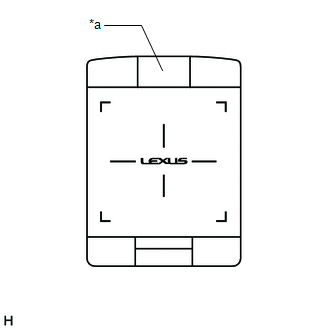
(2) Perform a flick operation on the remote touch screen from the left to the right 5 times and then perform a flick operation from the right to left 5 times with the screen and audio turned off as shown in the illustration.
HINT:
- Diagnostic mode can only be started if the above operation is completed within 15 seconds of the first flick from the left to the right.
- If the operation is not completed within 15 seconds of the first flick from the left to the right or fails, turn the screen and audio on and then off before attempting to start diagnostic mode again.
- Flick operations can be recognized anywhere within the touch area of the remote touch screen.
.png)
.png)
(3) Diagnostic mode will start and the "Service Menu" screen will be displayed.
FAILURE DIAGNOSIS
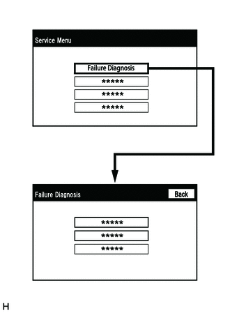
(a) The "Failure Diagnosis" screen will be displayed by pressing the "Failure Diagnosis" switch on the "Service Menu" screen.
SYSTEM CHECK
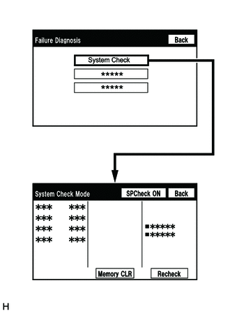
(a) The "System Check Mode" screen will be displayed by selecting "System Check" on the "Failure Diagnosis" screen.
CHECK DTC (CHECK USING SYSTEM CHECK MODE SCREEN)
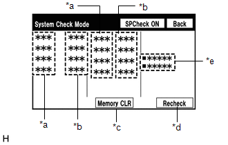
(a) System check mode screen description
 Screen Description
 | Display | Content |
|---|---|
| *a: Device Name List No. 1 |
|
| *b: Check Result | Result codes for all devices are displayed. |
| *c: Memory Clear |
|
| *d: Recheck |
|
| *e: Device Name List No. 2 |
|
| Name | Component | Connection Method |
|---|---|---|
| DCU | Radio receiver assembly | - |
| DSP-AMP | Stereo component amplifier assembly | AVC-LAN communication line |
| DISP | Multi-display assembly | AVC-LAN communication line |
| R-TOUCH | Remote touch (Remote operation controller assembly) | Local bus communication line |
| CLOCK | Clock assembly | Local bus communication line |
| CAA | Television camera assembly | Vehicle wire harness |
| Result | Meaning | Action |
|---|---|---|
| OK | The device does not respond with a DTC. | - |
| DETAIL | The device responds with a DTC. | Look up the DTC in "Unit Check Mode". |
| NCON | The device was previously present, but does not respond in diagnostic mode. |
|
| NRES | The device responds in diagnostic mode, but gives no DTC information. |
|
| Name | Component | Connection Method |
|---|---|---|
| *: w/ Manual (SOS) Switch | ||
| DCM | DCM (telematics transceiver)* | USB communication line |
| AUX/VTR | No. 1 stereo jack adapter assembly | Vehicle wire harness |
| IF-BOX_ USB | No. 1 stereo jack adapter assembly | USB communication line |
(b) Unit check mode screen description
.png) Screen Description
Screen Description | Display | Content |
|---|---|
| *: w/ GPS Time Setting Function | |
| *a: Device name | Target device |
| *b: History DTC | Diagnostic memory results and stored DTCs are displayed. |
| *c: Present DTC | DTCs output in the service check are displayed. |
| *d: DTC | DTC (Diagnostic Trouble Code) |
| *e: Timestamp* | The time and date of history DTCs are displayed. (The year is displayed in 2-digit format.) |
| *f: Diagnosis clear | Selecting "Code CLR" for 3 seconds clears the diagnostic memory data of the target device. (Both diagnostic system check result and the displayed data are cleared.) |
HINT:
- This screen is updated once per second.
- A maximum of 6 DTCs can be displayed for history and present DTCs.
(c) Read the system check result.
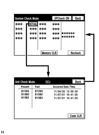
(1) If the check result is "DETAIL", select the displayed check result to view the results on the "Unit Check Mode" screen and record them.
NOTICE:
A maximum of 6 DTCs can be displayed for history and present DTCs on the "Unit Check Mode" screen. Therefore, when 6 DTCs are displayed, troubleshoot those DTCs first and then check the "Unit Check Mode" screen again to see if any other DTCs are displayed.
HINT:
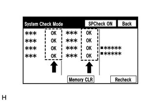
- When all results are "OK", no DTCs are stored.
-
When "NCON" is displayed for all devices connected via AVC-LAN communication, or when all device names are not displayed, check if there is a short circuit in an AVC-LAN line or devices connected to the AVC-LAN. Repair or replace parts as necessary.
Click here
- When proceeding to view the results of another device, select "Back" to return to the "System Check Mode" screen. Repeat the above step to view the results of other devices.
(2) Check the details of the DTC(s).
Click here
DTC CLEAR/RECHECK (CLEAR USING SYSTEM CHECK MODE SCREEN)
(a) Clear DTCs
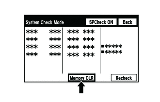
(1) Select "Memory CLR" for 3 seconds.
(2) Check that the check results are cleared.
HINT:
- To clear the DTCs for a specific device, use the "Unit Check Mode" screen.
- When clearing the DTCs using the "Unit Check Mode" screen, select "Code CLR" for 3 seconds.
(b) Recheck
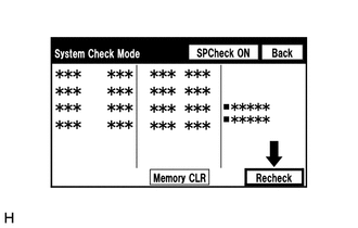
(1) Press the "Recheck" switch.
(2) Check that all diagnostic codes are "OK" when the check results are displayed. If a result other than "OK" is displayed, perform troubleshooting again.
HINT:
When the DTCs are cleared using the "Unit Check Mode" screen, select "Back" to return to the "System Check Mode" screen and perform this operation.
FINISH DIAGNOSTIC MODE
(a) Turn the engine switch off.
 Terminals Of Ecu
TERMINALS OF ECU HINT: Check from the rear of the connector while it is connected to the components. RADIO RECEIVER ASSEMBLY Terminal No. (Symbol) Wiring Color Terminal Description Condition ...
 Freeze Frame Data
FREEZE FRAME DATA CHECK FREEZE FRAME DATA (a) Connect the Techstream to the DLC3. (b) Turn the engine switch on (IG). (c) Turn the Techstream on. (d) Enter the following menus: Body Electrical / Navig ...
Other materials:
Lexus RX (RX 350L, RX450h) 2016-2026 Repair Manual > Dynamic Radar Cruise Control System: Data List / Active Test
DATA LIST / ACTIVE TEST NOTICE:
In the table below, the values listed under "Normal Condition" are reference values. Do not depend solely on these reference values when deciding whether a part is faulty or not.
When diagnosing symptoms such as hesitation, rough idle, or other small symptoms usi ...
Lexus RX (RX 350L, RX450h) 2016-2026 Repair Manual > Dynamic Radar Cruise Control System: Vehicle Control History
VEHICLE CONTROL HISTORY NOTICE: Make sure to record any output Vehicle Control History codes before clearing them and checking the Vehicle Control History again. CHECK VEHICLE CONTROL HISTORY (DYNAMIC RADAR CRUISE CONTROL SYSTEM) (a) Connect the Techstream to the DLC3. (b) Turn the engine switch on ...
Lexus RX (RX 350L, RX450h) 2016-{YEAR} Owners Manual
- For your information
- Pictorial index
- For safety and security
- Instrument cluster
- Operation of each component
- Driving
- Lexus Display Audio system
- Interior features
- Maintenance and care
- When trouble arises
- Vehicle specifications
- For owners
Lexus RX (RX 350L, RX450h) 2016-{YEAR} Repair Manual

0.0106