Lexus RX (RX 350L, RX450h) 2016-2026 Repair Manual: Electric Parking Brake Actuator Supply Voltage Circuit Voltage Below Threshold (C13B516)
DESCRIPTION
| DTC No. | Detection Item | DTC Detection Condition | Trouble Area | Memory | Note |
|---|---|---|---|---|---|
| C13B516 | Electric Parking Brake Actuator Supply Voltage Circuit Voltage Below Threshold |
HINT: *: When the battery voltage is 12 V. |
| DTC stored | An electric parking brake system malfunction is displayed on the multi-information display. |
| Vehicle Condition | |||
|---|---|---|---|
| Pattern 1 | Pattern 2 | ||
| Diagnosis Condition | Engine switch on (IG) | ○ | - |
| Electric parking brake switch assembly pulled to lock side with engine switch off | - | ○ | |
| Malfunction Status | Voltage at terminal +BS is less than 5.4 V* HINT: *: When the battery voltage is 12 V. | ○ | ○ |
| Detection Time | Approximately 0.5 seconds | Approximately 0.5 seconds | |
| Number of Trips | 1 trip | 1 trip | |
HINT:
DTC will be output when conditions for either of the patterns in the table above are met.
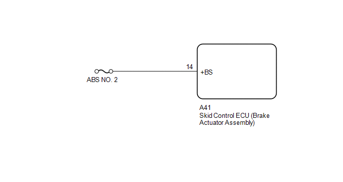
WIRING DIAGRAM
CAUTION / NOTICE / HINT
NOTICE:
- Inspect the fuses for circuits related to this system before performing the following procedure.
- The electric parking brake may still operate up to 20 seconds after the engine switch is turned off. Before disconnecting connectors or fuses, turn the engine switch off and wait 20 seconds or more.
-
After replacing the skid control ECU (brake actuator assembly), perform "Calibration".
Click here
.gif)
- When replacing the skid control ECU (brake actuator assembly), operate the electric parking brake switch (electric parking brake switch assembly) as the parking brake indicator light (red) blinks when the engine switch is first turned on (IG).
PROCEDURE
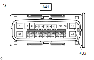
| 1. | CHECK HARNESS AND CONNECTOR (+BS TERMINAL VOLTAGE) |
(a) Disconnect the A41 skid control ECU (brake actuator assembly) connector.
| (b) Measure the voltage according to the value(s) in the table below. Standard Voltage:
|
|
| OK | .gif) | REPLACE SKID CONTROL ECU (BRAKE ACTUATOR ASSEMBLY) |
| NG | | REPAIR OR REPLACE HARNESS OR CONNECTOR |
 Right Electric Parking Brake Actuator Signal Stuck In Range (C06132A)
DESCRIPTION DTC No. Detection Item DTC Detection Condition Trouble Area Memory Note C06132A Right Electric Parking Brake Actuator Signal Stuck In Range
Diagnosis Condition:
Ele ...
 Supply Voltage Circuit IG Open (C123A14)
DESCRIPTION DTC No. Detection Item DTC Detection Condition Trouble Area Memory Note C123A14 Supply Voltage Circuit IG Open
Diagnosis Condition:
Engine switch on (IG)
Malfunct ...
Other materials:
Lexus RX (RX 350L, RX450h) 2016-2026 Repair Manual > Front Airbag Sensor: Installation
INSTALLATION CAUTION / NOTICE / HINT HINT:
Use the same procedure for the RH side and LH side.
The following procedure is for the LH side.
PROCEDURE 1. INSTALL FRONT AIRBAG SENSOR (a) Check that the engine switch is off. (b) Check that the cable is disconnected from the negative (-) battery ...
Lexus RX (RX 350L, RX450h) 2016-2026 Repair Manual > Wiper / Washer: Headlight Cleaner Actuator Cover
RemovalREMOVAL PROCEDURE 1. REMOVE HEADLIGHT WASHER COVER LH (a) Disengage the claw as indicated by the arrows, in the order shown in the illustration to remove the headlight washer cover LH. Remove in this Direction (1) Remove in this Direction (2) 2. REMOVE HEADLIGHT WASHER COVER ...
Lexus RX (RX 350L, RX450h) 2016-{YEAR} Owners Manual
- For your information
- Pictorial index
- For safety and security
- Instrument cluster
- Operation of each component
- Driving
- Lexus Display Audio system
- Interior features
- Maintenance and care
- When trouble arises
- Vehicle specifications
- For owners
Lexus RX (RX 350L, RX450h) 2016-{YEAR} Repair Manual

0.0089