Lexus RX (RX 350L, RX450h) 2016-2026 Repair Manual: Sensor (Motor) Failure (B2341,B2344)
DESCRIPTION
When the sliding roof ECU (sliding roof drive gear sub-assembly) detects a motor malfunction and the sliding roof operation is stopped, DTC B2341 is stored.
When the sliding roof ECU (sliding roof drive gear sub-assembly) detects a gear position malfunction and the sliding roof operation is stopped, DTC B2344 is stored.
| DTC No. | Detection Item | DTC Detection Condition | Trouble Area |
|---|---|---|---|
| B2341 | Sensor (Motor) Failure | Sensor (motor) failure (The sliding roof ECU (sliding roof drive gear sub-assembly) enters fail-safe mode due to a problem with the motor) |
|
| B2344 | Position Failure | Position failure (The sliding roof ECU (sliding roof drive gear sub-assembly) enters fail-safe mode due to a problem with the gear position) |
|
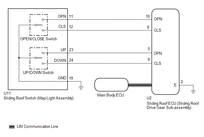
WIRING DIAGRAM
CAUTION / NOTICE / HINT
NOTICE:
-
If the sliding roof ECU (sliding roof drive gear sub-assembly) is removed and reinstalled or replaced, the sliding roof ECU (sliding roof drive gear sub-assembly) must be initialized.
Click here
.gif)
-
The sliding roof system uses the LIN communication system. First, confirm that there are no malfunctions in the LIN communication system. Refer to How to Proceed with Troubleshooting.
Click here
PROCEDURE
| 1. | CHECK SLIDING ROOF OPERATION |
(a) Check the sliding roof auto operation.
Click here
OK:
Auto operation operates normally.
| NG | .gif) | GO TO STEP 3 |
|
.gif)
| 2. | CHECK DTC OUTPUT |
(a) Clear the DTCs.
Click here
(b) Check for DTCs.
Body Electrical > Sliding Roof > Trouble CodesOK:
DTCs B2341 and B2344 are not output.
| OK | | USE SIMULATION METHOD TO CHECK |
| NG | | REPLACE SLIDING ROOF ECU (SLIDING ROOF DRIVE GEAR SUB-ASSEMBLY) |
| 3. | INITIALIZE SLIDING ROOF ECU (SLIDING ROOF DRIVE GEAR SUB-ASSEMBLY) |
(a) Check that the sliding roof ECU (sliding roof drive gear sub-assembly) can be initialized.
Click here
OK:
Sliding roof ECU (sliding roof drive gear sub-assembly) can be initialized.
| NG | | GO TO STEP 5 |
|
| 4. | CHECK DTC OUTPUT |
(a) Clear the DTCs.
Click here
(b) Check for DTCs.
Body Electrical > Sliding Roof > Trouble CodesOK:
DTCs B2341 and B2344 are not output.
| OK | | END (MALFUNCTION DUE TO INITIALIZATION FAILURE) |
| NG | | REPLACE SLIDING ROOF ECU (SLIDING ROOF DRIVE GEAR SUB-ASSEMBLY) |
| 5. | CHECK HARNESS AND CONNECTOR (SLIDING ROOF ECU (SLIDING ROOF DRIVE GEAR SUB-ASSEMBLY) - SLIDING ROOF SWITCH (MAP LIGHT ASSEMBLY) AND BODY GROUND) |
(a) Disconnect the U11 sliding roof switch (map light assembly) connector.
(b) Disconnect the U2 sliding roof ECU (sliding roof drive gear sub-assembly) connector.
(c) Measure the resistance according to the value(s) in the table below.
Standard Resistance:
| Tester Connection | Condition | Specified Condition |
|---|---|---|
| U2-8 (CLS) - U11-12 (CLS) | Always | Below 1 Ω |
| U2-8 (CLS) or U11-12 (CLS) - Body ground | Always | 10 kΩ or higher |
| U2-10 (OPN) - U11-11 (OPN) | Always | Below 1 Ω |
| U2-10 (OPN) or U11-11 (OPN) - Body ground | Always | 10 kΩ or higher |
| U2-9 (CLS) - U11-24 (DOWN) | Always | Below 1 Ω |
| U2-9 (CLS) or U11-24 (DOWN) - Body ground | Always | 10 kΩ or higher |
| U2-5 (OPN) - U11-23 (UP) | Always | Below 1 Ω |
| U2-5 (OPN) or U11-23 (UP) - Body ground | Always | 10 kΩ or higher |
| U11-19 (GND) - Body ground | Always | Below 1 Ω |
| U2-2 (E) - Body ground | Always | Below 1 Ω |
| NG | | REPAIR OR REPLACE HARNESS OR CONNECTOR |
|
| 6. | INSPECT SLIDING ROOF SWITCH (MAP LIGHT ASSEMBLY) |
(a) Remove the sliding roof switch (map light assembly).
Click here
(b) Inspect the sliding roof switch (map light assembly).
Click here
| OK | | REPLACE SLIDING ROOF ECU (SLIDING ROOF DRIVE GEAR SUB-ASSEMBLY) |
| NG | | REPLACE SLIDING ROOF SWITCH (MAP LIGHT ASSEMBLY) |
 Diagnostic Trouble Code Chart
DIAGNOSTIC TROUBLE CODE CHART Sliding Roof System DTC No. Detection Item Link B2341 Sensor (Motor) Failure B2342 Switch Failure B2343 Position Initialization Incompl ...
 Switch Failure (B2342)
DESCRIPTION This DTC is stored when the sliding roof ECU (sliding roof drive gear sub-assembly) detects that the sliding roof switch (map light assembly) is stuck for 30 seconds or more. DTC No. ...
Other materials:
Lexus RX (RX 350L, RX450h) 2016-2026 Repair Manual > Exhaust Pipe: Installation
INSTALLATION PROCEDURE 1. INSTALL HEATED OXYGEN SENSOR (for Bank 2) Click here 2. INSTALL FRONT EXHAUST PIPE ASSEMBLY (a) Install a new exhaust pipe gasket to the front exhaust pipe assembly. (b) Install the front exhaust pipe assembly to the exhaust manifold assembly LH (TWC: Front Catalyst) with ...
Lexus RX (RX 350L, RX450h) 2016-2026 Repair Manual > Glove Box Light: Inspection
INSPECTION PROCEDURE 1. INSPECT GLOVE BOX LIGHT ASSEMBLY (a) Inspect the glove box light. (1) Apply battery voltage to each terminal of glove box light assembly connector and check the operation of the glove box light. Result: Connection Specified Condition Battery positive (+) → 2 Ba ...
Lexus RX (RX 350L, RX450h) 2016-{YEAR} Owners Manual
- For your information
- Pictorial index
- For safety and security
- Instrument cluster
- Operation of each component
- Driving
- Lexus Display Audio system
- Interior features
- Maintenance and care
- When trouble arises
- Vehicle specifications
- For owners
Lexus RX (RX 350L, RX450h) 2016-{YEAR} Repair Manual

0.0138