Lexus RX (RX 350L, RX450h) 2016-2026 Repair Manual: Removal
REMOVAL
PROCEDURE
1. REMOVE BACK DOOR OUTSIDE GARNISH SUB-ASSEMBLY
Click here .gif)
2. REMOVE REAR SPOILER
Click here
3. REMOVE POWER BACK DOOR SENSOR ASSEMBLY LH
Click here
4. REMOVE POWER BACK DOOR SENSOR ASSEMBLY RH
HINT:
Use the same procedure as for the LH side.
5. REMOVE REAR WIPER ARM AND BLADE ASSEMBLY (w/o Rear No. 2 Seat)
Click here
6. REMOVE REAR WIPER MOTOR AND BRACKET ASSEMBLY (w/ Rear No. 2 Seat)
Click here
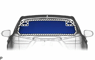
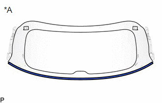
7. REMOVE BACK DOOR GLASS SUB-ASSEMBLY
(a) Disconnect each connector and disengage each clamp.
(b) Apply protective tape to the area around the installation position of the back door glass sub-assembly on the back door panel to prevent it from being scratched.
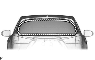
.png) | Protective Tape |
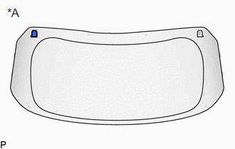
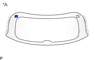
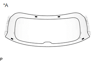
| (c) Place matchmarks on the back door glass sub-assembly and back door panel at the locations indicated in the illustration. HINT: Matchmarks are not necessary if the back door glass is not going to be reused. |
|

| (d) Pass a piano wire between the back door panel and back door glass sub-assembly from the interior. |
|
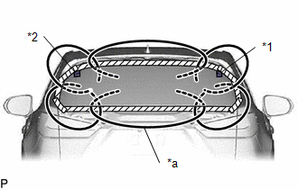
(e) Tie both wire ends to wooden blocks or similar objects that can serve as handles.
(f) Cut the adhesive by pulling the piano wire around the back door glass.
NOTICE:
- When separating the back door glass, take care not to damage the paint or interior and exterior ornaments.
- When cutting the adhesive, take care not to damage the connectors on the back door glass sub-assembly.
- Do not pull the piano wire in a vertical direction, but pull it in a horizontal direction.
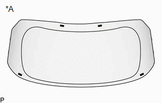
| (g) Using suction cups, disengage the No. 1 back window glass spacer and No. 2 back window glass spacer and remove the back door glass sub-assembly. NOTICE:
|
|
8. REMOVE LOWER BACK WINDOW MOULDING (w/o Rear No. 2 Seat)
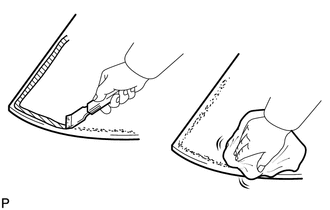
(a) When reusing the back door glass:
| (1) Using a scraper, remove the lower back window moulding. NOTICE:
|
|
9. REMOVE LOWER BACK WINDOW MOULDING (w/ Rear No. 2 Seat)
(a) When reusing the back door glass:
| (1) Using a scraper, remove the lower back window moulding. NOTICE:
|
|
10. REMOVE NO. 1 BACK WINDOW GLASS SPACER (w/o Rear No. 2 Seat)
(a) When reusing the back door glass:
| (1) Using a scraper, remove the No. 1 back window glass spacer. NOTICE:
|
|
11. REMOVE NO. 2 BACK WINDOW GLASS SPACER (w/o Rear No. 2 Seat)
HINT:
Use the same procedure as for the No. 1 back window glass spacer.
12. REMOVE NO. 1 BACK WINDOW GLASS SPACER (w/ Rear No. 2 Seat)
(a) When reusing the back door glass:
| (1) Using a scraper, remove the No. 1 back window glass spacer. NOTICE:
|
|
13. REMOVE NO. 2 BACK WINDOW GLASS SPACER (w/ Rear No. 2 Seat)
HINT:
Use the same procedure as for the No. 1 back window glass spacer.
14. REMOVE BACK DOOR GLASS SPACER (w/o Rear No. 2 Seat)
(a) When reusing the back door glass:
| (1) Using a scraper, remove the 4 back door glass spacers. NOTICE:
|
|
15. REMOVE BACK DOOR GLASS SPACER (w/ Rear No. 2 Seat)
(a) When reusing the back door glass:
| (1) Using a scraper, remove the 4 back door glass spacers. NOTICE:
|
|
16. CLEAN BACK DOOR GLASS
(a) When reusing the back door glass:
| (1) Using a scraper, remove any remaining adhesive residue from the back door glass. NOTICE: Be careful not to damage the back door glass. |
|
(2) Clean the outer circumference of the back door glass with a non-residue solvent.
NOTICE:
- Do not touch the back door glass surface after cleaning it.
- Even if using a new back door glass, clean it with a non-residue solvent.
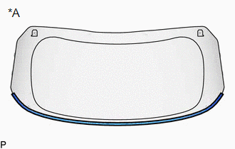
17. CLEAN BACK DOOR PANEL
(a) Clean and shape the contact surfaces of the back door panel.
(1) Using a knife, cut off any excess adhesive on the contact surfaces of the back door panel as shown in the illustration.
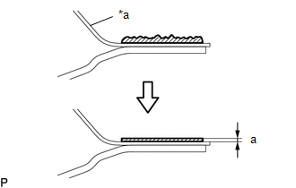
| *a | Back Door Panel |
| | Adhesive |
Standard Dimension:
| Area | Dimension |
|---|---|
| a | 1.0 mm (0.0394 in.) or more |
NOTICE:
Be careful not to damage the back door panel.
HINT:
Leave as much adhesive on the back door panel as possible.
(2) Clean the contact surfaces of the back door panel with a piece of cloth saturated with non-residue solvent.
HINT:
Even if all of the adhesive has been removed, clean the back door panel.
 Components
COMPONENTS ILLUSTRATION *A w/o Rear No. 2 Seat - - *1 BACK DOOR GLASS *2 BACK DOOR GLASS SPACER *3 BACK DOOR GLASS SUB-ASSEMBLY *4 LOWER BACK WINDOW MOULDING *5 NO. ...
 Installation
INSTALLATION PROCEDURE 1. INSTALL BACK DOOR GLASS SPACER (w/o Rear No. 2 Seat) (a) Using a brush or sponge, coat the installation area of 4 new back door glass spacers with primer G. NOTICE:
Do not ...
Other materials:
Lexus RX (RX 350L, RX450h) 2016-2026 Owners Manual > Lexus Display
Audio system: Using the audio system
Selecting the audio
source
Switching between audio sources, such as the radio and CD, is explained
in
this section.
Changing audio source
1. Press the "AUDIO" button to display the "Source" screen.
If the "Source" screen is not displayed, press the button again.
2. Select the desired audi ...
Lexus RX (RX 350L, RX450h) 2016-2026 Repair Manual > Power Steering System: Calibration
CALIBRATION TORQUE SENSOR ZERO POINT CALIBRATION (USING TECHSTREAM) NOTICE: Perform torque sensor zero point calibration if any of the following conditions occur:
The power steering ECU assembly has been replaced.
The electric power steering column sub-assembly has been replaced.
There is a d ...
Lexus RX (RX 350L, RX450h) 2016-{YEAR} Owners Manual
- For your information
- Pictorial index
- For safety and security
- Instrument cluster
- Operation of each component
- Driving
- Lexus Display Audio system
- Interior features
- Maintenance and care
- When trouble arises
- Vehicle specifications
- For owners
Lexus RX (RX 350L, RX450h) 2016-{YEAR} Repair Manual

0.0113