Lexus RX (RX 350L, RX450h) 2016-2026 Repair Manual: GVIF Disconnected (from Extension Module to H/U) (B153A)
DESCRIPTION
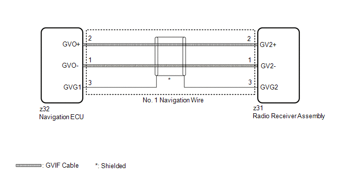
The radio receiver assembly and navigation ECU are connected via video signal (digital) lines.
This DTC is stored when a video signal (digital) line is disconnected.
| DTC No. | Detection Item | DTC Detection Condition | Trouble Area |
|---|---|---|---|
| B153A | GVIF Disconnected (from Extension Module to H/U) | GVIF disconnected (from navigation ECU to radio receiver assembly) |
|
WIRING DIAGRAM
CAUTION / NOTICE / HINT
NOTICE:
Depending on the parts that are replaced during vehicle inspection or maintenance, performing initialization, registration or calibration may be needed. Refer to Precaution for Navigation System.
Click here .gif)
PROCEDURE
| 1. | CHECK DTC |
(a) Clear the DTCs.
Body Electrical > Navigation System > Clear DTCs(b) Turn the engine switch off.
(c) Turn the engine switch on (IG).
(d) Press the "MAP" switch and check for DTCs.
Body Electrical > Navigation System > Trouble CodesOK:
No DTCs are output.
| OK |  | USE SIMULATION METHOD TO CHECK |
|

| 2. | CHECK NO. 1 NAVIGATION WIRE (RADIO RECEIVER ASSEMBLY - NAVIGATION ECU) |
| (a) Disconnect the z31 radio receiver assembly connector. |
|
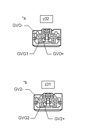
(b) Disconnect the z32 navigation ECU connector.
(c) Measure the resistance according to the value(s) in the table below.
Standard Resistance:
| Tester Connection | Condition | Specified Condition |
|---|---|---|
| z31-1 (GV2-) - z32-1 (GVO-) | Always | Below 1 Ω |
| z31-2 (GV2+) - z32-2 (GVO+) | Always | Below 1 Ω |
| z31-3 (GVG2) - z32-3 (GVG1) | Always | Below 1 Ω |
| NG | | REPLACE NO. 1 NAVIGATION WIRE |
|
| 3. | REPLACE NAVIGATION ECU |
(a) Replace the navigation ECU with a new or known good one.
Click here
|
| 4. | CHECK DTC |
(a) Clear the DTCs.
Body Electrical > Navigation System > Clear DTCs(b) Turn the engine switch off.
(c) Turn the engine switch on (IG).
(d) Press the "MAP" switch and check for DTCs.
Body Electrical > Navigation System > Trouble CodesOK:
No DTCs are output.
| OK | | END (NAVIGATION ECU IS DEFECTIVE) |
| NG | | REPLACE RADIO RECEIVER ASSEMBLY |
 NTSC Disconnected (from Park Assist/Monitoring ECU) (B1535,C1622)
DESCRIPTION These DTCs are stored if the radio receiver assembly judges that the signals or signal lines between the rear television camera assembly and the multi-display assembly are not normal as a ...
 Operation Check
OPERATION CHECK CHECK NAVIGATION SYSTEM NORMAL CONDITION (a) If the cause of a symptom is any of the following, the corresponding symptom is normal; it is not due to a malfunction. Symptom Answer ...
Other materials:
Lexus RX (RX 350L, RX450h) 2016-2026 Repair Manual > Rear Power Seat Control System(for Second Row): Terminals Of Ecu
TERMINALS OF ECU CHECK FOLD SEAT CONTROL ECU RH (a) Disconnect the x3 and x4 fold seat control ECU RH connectors. (b) Measure the resistance and voltage according to the value(s) in the table below. Terminal No. (Symbol) Wiring Color Terminal Description Condition Specified Condition ...
Lexus RX (RX 350L, RX450h) 2016-2026 Repair Manual > Headup Display System: Main Switch Circuit
DESCRIPTION The headup display switch assembly (integration control and panel assembly) and headup display (meter mirror sub-assembly) are connected via direct line. The headup display (meter mirror sub-assembly) can be turned off and on by operating the headup display switch assembly (integration c ...
Lexus RX (RX 350L, RX450h) 2016-{YEAR} Owners Manual
- For your information
- Pictorial index
- For safety and security
- Instrument cluster
- Operation of each component
- Driving
- Lexus Display Audio system
- Interior features
- Maintenance and care
- When trouble arises
- Vehicle specifications
- For owners
Lexus RX (RX 350L, RX450h) 2016-{YEAR} Repair Manual

0.0132